
An optical attenuator, or fiber optic attenuator, is a device used to reduce the power level of an optical signal, either in free space or in an optical fiber. The basic types of optical attenuators are fixed, step-wise variable, and continuously variable.
A transmission medium is a system or substance that can mediate the propagation of signals for the purposes of telecommunication. Signals are typically imposed on a wave of some kind suitable for the chosen medium. For example, data can modulate sound, and a transmission medium for sounds may be air, but solids and liquids may also act as the transmission medium. Vacuum or air constitutes a good transmission medium for electromagnetic waves such as light and radio waves. While material substance is not required for electromagnetic waves to propagate, such waves are usually affected by the transmission media they pass through, for instance, by absorption or reflection or refraction at the interfaces between media. Technical devices can therefore be employed to transmit or guide waves. Thus, an optical fiber or a copper cable is used as transmission media.

A cleave in an optical fiber is a deliberate, controlled break, intended to create a perfectly flat end face perpendicular to the fiber's longitudinal axis. The process of cleaving an optical fiber forms one of the steps in the preparation for a fiber splice operation, regardless of the subsequent splice being a fusion splice or a mechanical splice; the other steps in the preparation being those of stripping and fiber alignment. A good cleave is required for a successful low loss splice of an optical fiber, often it is the case that fibers spliced by identical methods tend to have different losses, this difference can often be attributed to the quality of their initial cleaves.

An optical fiber connector joins optical fibers, and enables quicker connection and disconnection than splicing. The connectors mechanically couple and align the cores of fibers so light can pass. Better connectors lose very little light due to reflection or misalignment of the fibers. In all, about 100 different types of fiber optic connectors have been introduced to the market.

A polarimeter is a scientific instrument used to measure the angle of rotation caused by passing polarized light through an optically active substance.

An optical fiber, or optical fibre in Commonwealth English, is a flexible, transparent fiber made by drawing glass (silica) or plastic to a diameter slightly thicker than that of a human hair. Optical fibers are used most often as a means to transmit light between the two ends of the fiber and find wide usage in fiber-optic communications, where they permit transmission over longer distances and at higher bandwidths than electrical cables. Fibers are used instead of metal wires because signals travel along them with less loss; in addition, fibers are immune to electromagnetic interference, a problem from which metal wires suffer. Fibers are also used for illumination and imaging, and are often wrapped in bundles so they may be used to carry light into, or images out of confined spaces, as in the case of a fiberscope. Specially designed fibers are also used for a variety of other applications, some of them being fiber optic sensors and fiber lasers.

A mirror mount is a device that holds a mirror. In optics research, these can be quite sophisticated devices, due to the need to be able to tip and tilt the mirror by controlled amounts, while still holding it in a precise position when it is not being adjusted.

Fiber-optic communication is a method of transmitting information from one place to another by sending pulses of infrared or visible light through an optical fiber. The light is a form of carrier wave that is modulated to carry information. Fiber is preferred over electrical cabling when high bandwidth, long distance, or immunity to electromagnetic interference is required. This type of communication can transmit voice, video, and telemetry through local area networks or across long distances.
An optical ground wire is a type of cable that is used in overhead power lines. Such cable combines the functions of grounding and communications. An OPGW cable contains a tubular structure with one or more optical fibers in it, surrounded by layers of steel and aluminum wire. The OPGW cable is run between the tops of high-voltage electricity pylons. The conductive part of the cable serves to bond adjacent towers to earth ground, and shields the high-voltage conductors from lightning strikes. The optical fibers within the cable can be used for high-speed transmission of data, either for the electrical utility's own purposes of protection and control of the transmission line, for the utility's own voice and data communication, or may be leased or sold to third parties to serve as a high-speed fiber interconnection between cities.

Fusion splicing is the act of joining two optical fibers end-to-end. The goal is to fuse the two fibers together in such a way that light passing through the fibers is not scattered or reflected back by the splice, and so that the splice and the region surrounding it are almost as strong as the intact fiber. The source of heat used to melt and fuse the two glass fibers being spliced is usually an electric arc, but can also be a laser, a gas flame, or a tungsten filament through which current is passed.

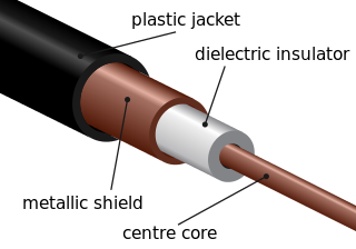
A fiber-optic cable, also known as an optical-fiber cable, is an assembly similar to an electrical cable but containing one or more optical fibers that are used to carry light. The optical fiber elements are typically individually coated with plastic layers and contained in a protective tube suitable for the environment where the cable is used. Different types of cable are used for optical communication in different applications, for example long-distance telecommunication or providing a high-speed data connection between different parts of a building.
Fiber cable termination is the addition of connectors to each optical fiber in a cable. The fibers need to have connectors fitted before they can attach to other equipment. Two common solutions for fiber cable termination are pigtails and fanout kits or breakout kits.

The FC connector is a fiber-optic connector with a threaded body, which was designed for use in high-vibration environments. It is commonly used with both single-mode optical fiber and polarization-maintaining optical fiber. FC connectors are used in datacom, telecommunications, measurement equipment, and single-mode lasers. They are becoming less common, displaced by SC and LC connectors. The FC connector has been standardized in TIA fiber optic connector intermateability standard EIA/TIA-604-4.
A fiber management system (FMS) manages optical fiber connections from outside of fiber rack to the fiber routers. Fiber-optic cable duct containing many fibers comes from far end sites and terminates on the FMS using splicing technology. FMS has fiber in and fiber out ports. From fiber out port the fiber patch will go to fiber optics based router.
Nyfors Teknologi AB is a high-end supplier of advanced optical fiber handling equipment, based in Stockholm, Sweden. The company develops and manufactures equipment used in optical fiber fusion splicing, including products for stripping and preparation, testing and analysing and fiber end-face inspection, but is most well known for its automated optical fiber recoating and fiber cleaving systems. Nyfors products are sold internationally to customers within a wide range of industrial sectors and to public and private research institutions.
Recoating is the process of restoring the primary coating to stripped optical fiber sections after fusion splicing. In the recoating process, the spliced fiber is restored to its original shape and strength, using a recoater. The stripped fiber section is recoated by filling a recoating resin, usually acrylate into transparent moulds. The resin is then cured with UV light. It is often desirable to perform a proof-test after recoating, to ensure that the splice is strong enough to survive handling, packaging and extended use.

Stripping is the act of removing the protective polymer coating around optical fiber in preparation for fusion splicing. The splicing process begins by preparing both fiber ends for fusion, which requires that all protective coating is removed or stripped from the ends of each fiber. Fiber optical stripping can be done using a special stripping and preparation unit that uses hot sulphuric acid or a controlled flow of hot air to remove the coating. There are also mechanical tools used for stripping fiber which are similar to copper wire strippers. Fiber optical stripping and preparation equipment used in fusion splicing is commercially available through a small number of specialized companies, which usually also design machines used for fiber optical recoating.
A fiber-optic splitter, also known as a beam splitter, is based on a quartz substrate of an integrated waveguide optical power distribution device, similar to a coaxial cable transmission system. The optical network system uses an optical signal coupled to the branch distribution. The fiber optic splitter is one of the most important passive devices in the optical fiber link. It is an optical fiber tandem device with many input and output terminals, especially applicable to a passive optical network to connect the main distribution frame and the terminal equipment and to branch the optical signal.
All-dielectric self-supporting (ADSS) cable is a type of optical fiber cable that is strong enough to support itself between structures without using conductive metal elements. It is used by electrical utility companies as a communications medium, installed along existing overhead transmission lines and often sharing the same support structures as the electrical conductors.
In telecommunications, a line splice is a method of connecting electrical cables or optical fibers.
