The die from an Intel 8742, an 8-bit microcontroller that includes a CPU, 128 bytes of RAM, 2048 bytes of EPROM, and I/O "data" on current chipA circuit built on a printed circuit board (PCB)
An electronic circuit is composed of individual electronic components, such as resistors, transistors, capacitors, inductors and diodes, connected by conductive wires or traces through which electric current can flow. It is a type of electrical circuit. For a circuit to be referred to as electronic, rather than electrical, generally at least one active component must be present. The combination of components and wires allows various simple and complex operations to be performed: signals can be amplified, computations can be performed, and data can be moved from one place to another.[1]
Circuits can be constructed of discrete components connected by individual pieces of wire, but today it is much more common to create interconnections by photolithographic techniques on a laminated substrate (a printed circuit board or PCB) and solder the components to these interconnections to create a finished circuit. In an integrated circuit or IC, the components and interconnections are formed on the same substrate, typically a semiconductor such as doped silicon or (less commonly) gallium arsenide.[2]
A circuit diagram representing an analog circuit, in this case a simple amplifier
Analog electronic circuits are those in which current or voltage may vary continuously with time to correspond to the information being represented.
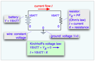
A simple schematic showing wires, a resistor, and a battery
The basic components of analog circuits are wires, resistors, capacitors, inductors, diodes, and transistors. Analog circuits are very commonly represented in schematic diagrams, in which wires are shown as lines, and each component has a unique symbol. Analog circuit analysis employs Kirchhoff's circuit laws: all the currents at a node (a place where wires meet), and the voltage around a closed loop of wires is 0. Wires are usually treated as ideal zero-voltage interconnections; any resistance or reactance is captured by explicitly adding a parasitic element, such as a discrete resistor or inductor. Active components such as transistors are often treated as controlled current or voltage sources: for example, a field-effect transistor can be modeled as a current source from the source to the drain, with the current controlled by the gate-source voltage.
When the circuit size is comparable to a wavelength of the relevant signal frequency, a more sophisticated approach must be used, the distributed-element model. Wires are treated as transmission lines, with nominally constant characteristic impedance, and the impedances at the start and end determine transmitted and reflected waves on the line. Circuits designed according to this approach are distributed-element circuits. Such considerations typically become important for circuit boards at frequencies above a GHz; integrated circuits are smaller and can be treated as lumped elements for frequencies less than 10GHz or so.
In digital electronic circuits, electric signals take on discrete values, to represent logical and numeric values.[4] These values represent the information that is being processed. In the vast majority of cases, binary encoding is used: one voltage (typically the more positive value) represents a binary '1' and another voltage (usually a value near the ground potential, 0 V) represents a binary '0'. Digital circuits make extensive use of transistors, interconnected to create logic gates that provide the functions of Boolean logic: AND, NAND, OR, NOR, XOR and combinations thereof. Transistors interconnected so as to provide positive feedback are used as latches and flip flops, circuits that have two or more metastable states, and remain in one of these states until changed by an external input. Digital circuits therefore can provide logic and memory, enabling them to perform arbitrary computational functions. (Memory based on flip-flops is known as static random-access memory (SRAM). Memory based on the storage of charge in a capacitor, dynamic random-access memory (DRAM), is also widely used.)
The design process for digital circuits is fundamentally different from the process for analog circuits. Each logic gate regenerates the binary signal, so the designer need not account for distortion, gain control, offset voltages, and other concerns faced in an analog design. As a consequence, extremely complex digital circuits, with billions of logic elements integrated on a single silicon chip, can be fabricated at low cost. Such digital integrated circuits are ubiquitous in modern electronic devices, such as calculators, mobile phone handsets, and computers. As digital circuits become more complex, issues of time delay, logic races, power dissipation, non-ideal switching, on-chip and inter-chip loading, and leakage currents, become limitations to circuit density, speed and performance.
Digital circuitry is used to create general purpose computing chips, such as microprocessors, and custom-designed logic circuits, known as application-specific integrated circuit (ASICs). Field-programmable gate arrays (FPGAs), chips with logic circuitry whose configuration can be modified after fabrication, are also widely used in prototyping and development.
Mixed-signal or hybrid circuits contain elements of both analog and digital circuits. Examples include comparators, timers, phase-locked loops, analog-to-digital converters, and digital-to-analog converters. Most modern radio and communications circuitry uses mixed signal circuits. For example, in a receiver, analog circuitry is used to amplify and frequency-convert signals so that they reach a suitable state to be converted into digital values, after which further signal processing can be performed in the digital domain.
A simple electronic circuit prototype on a breadboardExample of prototype in optoelectronics (Texas Instruments, DLP Cinema Prototype System)
In electronics, prototyping means building an actual circuit to a theoretical design to verify that it works, and to provide a physical platform for debugging it if it does not. The prototype is often constructed using techniques such as wire wrapping or using a breadboard, stripboard or perfboard, with the result being a circuit that is electrically identical to the design but not physically identical to the final product.[5]
Open-source tools like Fritzing exist to document electronic prototypes (especially the breadboard-based ones) and move toward physical production. Prototyping platforms such as Arduino also simplify the task of programming and interacting with a microcontroller.[6] The developer can choose to deploy their invention as-is using the prototyping platform, or replace it with only the microcontroller chip and the circuitry that is relevant to their product.
A technician can quickly build a prototype (and make additions and modifications) using these techniques, but for volume production it is much faster and usually cheaper to mass-produce custom printed circuit boards than to produce these other kinds of prototype boards. The proliferation of quick-turn PCB fabrication and assembly companies has enabled the concepts of rapid prototyping to be applied to electronic circuit design. It is now possible, even with the smallest passive components and largest fine-pitch packages, to have boards fabricated, assembled, and even tested in a matter of days.
References
↑ Charles Alexander and Matthew Sadiku (2004). Fundamentals of Electric Circuits. McGraw-Hill.
↑ Richard Jaeger (1997). Microelectronic Circuit Design. McGraw-Hill.
This page is based on this Wikipedia article Text is available under the CC BY-SA 4.0 license; additional terms may apply. Images, videos and audio are available under their respective licenses.