In microelectronics, a dual in-line package is an electronic component package with a rectangular housing and two parallel rows of electrical connecting pins. The package may be through-hole mounted to a printed circuit board (PCB) or inserted in a socket. The dual-inline format was invented by Don Forbes, Rex Rice and Bryant Rogers at Fairchild R&D in 1964, when the restricted number of leads available on circular transistor-style packages became a limitation in the use of integrated circuits. Increasingly complex circuits required more signal and power supply leads ; eventually microprocessors and similar complex devices required more leads than could be put on a DIP package, leading to development of higher-density chip carriers. Furthermore, square and rectangular packages made it easier to route printed-circuit traces beneath the packages.

Wire wrap is an electronic component assembly technique that was invented to wire telephone crossbar switches, and later adapted to construct electronic circuit boards. Electronic components mounted on an insulating board are interconnected by lengths of insulated wire run between their terminals, with the connections made by wrapping several turns of uninsulated sections of the wire around a component lead or a socket pin.

A printed circuit board (PCB), also called printed wiring board (PWB), is a medium used to connect or "wire" components to one another in a circuit. It takes the form of a laminated sandwich structure of conductive and insulating layers: each of the conductive layers is designed with a pattern of traces, planes and other features etched from one or more sheet layers of copper laminated onto or between sheet layers of a non-conductive substrate. Electrical components may be fixed to conductive pads on the outer layers, generally by means of soldering, which both electrically connects and mechanically fastens the components to the board. Another manufacturing process adds vias, drilled holes that allow electrical interconnections between conductive layers.

In electronics, point-to-point construction is a non-automated technique for constructing circuits which was widely used before the use of printed circuit boards (PCBs) and automated assembly gradually became widespread following their introduction in the 1950s. Circuits using thermionic valves were relatively large, relatively simple, and used large sockets, all of which made the PCB less obviously advantageous than with later complex semiconductor circuits. Point-to-point construction is still widespread in power electronics, where components are bulky and serviceability is a consideration, and to construct prototype equipment with few or heavy electronic components. A common practice, especially in older point-to-point construction, is to use the leads of components such as resistors and capacitors to bridge as much of the distance between connections as possible, reducing the need to add additional wire between the components.

A prototype is an early sample, model, or release of a product built to test a concept or process. It is a term used in a variety of contexts, including semantics, design, electronics, and software programming. A prototype is generally used to evaluate a new design to enhance precision by system analysts and users. Prototyping serves to provide specifications for a real, working system rather than a theoretical one. Physical prototyping has a long history, and paper prototyping and virtual prototyping now extensively complement it. In some design workflow models, creating a prototype is the step between the formalization and the evaluation of an idea.

A breadboard, solderless breadboard, or protoboard is a construction base used to build semi-permanent prototypes of electronic circuits. Unlike a perfboard or stripboard, breadboards do not require soldering or destruction of tracks and are hence reusable. For this reason, breadboards are also popular with students and in technological education.

Surface-mount technology (SMT), originally called planar mounting, is a method in which the electrical components are mounted directly onto the surface of a printed circuit board (PCB). An electrical component mounted in this manner is referred to as a surface-mount device (SMD). In industry, this approach has largely replaced the through-hole technology construction method of fitting components, in large part because SMT allows for increased manufacturing automation which reduces cost and improves quality. It also allows for more components to fit on a given area of substrate. Both technologies can be used on the same board, with the through-hole technology often used for components not suitable for surface mounting such as large transformers and heat-sinked power semiconductors.

Stripboard is the generic name for a widely used type of electronics prototyping material for circuit boards characterized by a pre-formed 0.1 inches (2.54 mm) regular (rectangular) grid of holes, with wide parallel strips of copper cladding running in one direction all the way along one side of an insulating bonded paper board. It is commonly also known by the name of the original product Veroboard, which is a trademark, in the UK, of British company Vero Technologies Ltd and Canadian company Pixel Print Ltd. It was originated and developed in the early 1960s by the Electronics Department of Vero Precision Engineering Ltd (VPE). It was introduced as a general-purpose material for use in constructing electronic circuits - differing from purpose-designed printed circuit boards (PCBs) in that a variety of electronics circuits may be constructed using a standard wiring board.

In electronics, through-hole technology is a manufacturing scheme in which leads on the components are inserted through holes drilled in printed circuit boards (PCB) and soldered to pads on the opposite side, either by manual assembly or by the use of automated insertion mount machines.

An electronic kit is a package of electrical components used to build an electronic device. Generally, kits are composed of electronic components, a circuit diagram (schematic), assembly instructions, and often a printed circuit board (PCB) or another type of prototyping board.

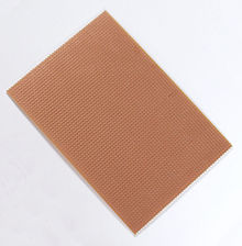
Perfboard is a material for prototyping electronic circuits. It is a thin, rigid sheet with holes pre-drilled at standard intervals across a grid, usually a square grid of 0.1 inches (2.54 mm) spacing. These holes are ringed by round or square copper pads, though bare boards are also available. Inexpensive perfboard may have pads on only one side of the board, while better quality perfboard can have pads on both sides. Since each pad is electrically isolated, the builder makes all connections with either wire wrap or miniature point to point wiring techniques. Discrete components are soldered to the prototype board such as resistors, capacitors, and integrated circuits. The substrate is typically made of paper laminated with phenolic resin or a fiberglass-reinforced epoxy laminate (FR-4).

In electronics, turret boards were an early attempt at making circuits that were relatively rugged, producible, and serviceable in the days before printed circuit boards (PCBs). As this method was somewhat more expensive than conventional "point-to-point" wiring techniques, it was generally found in the more expensive components, such as professional, commercial, and military audio and test equipment. This is similar to cordwood construction.
An electronic circuit is composed of individual electronic components, such as resistors, transistors, capacitors, inductors and diodes, connected by conductive wires or traces through which electric current can flow. It is a type of electrical circuit. For a circuit to be referred to as electronic, rather than electrical, generally at least one active component must be present. The combination of components and wires allows various simple and complex operations to be performed: signals can be amplified, computations can be performed, and data can be moved from one place to another.
Solder mask, solder stop mask or solder resist is a thin lacquer-like layer of polymer that is usually applied to the copper traces of a printed circuit board (PCB) for protection against oxidation and to prevent solder bridges from forming between closely spaced solder pads. Soldermask is a printed circuit board (PCB) manufacturing process that uses a chemical or thermosetting resin to coat a thin film on a circuit board, which can effectively form a layer of reliable protection to avoid unwanted short-circuiting and leakage of the circuit board, and to improve the reliability and electrical performance of the circuit board. A solder bridge is an unintended electrical connection between two conductors by means of a small blob of solder. PCBs use solder masks to prevent this from happening. Solder mask is not always used for hand soldered assemblies, but is essential for mass-produced boards that are soldered automatically using reflow or wave soldering techniques. Once applied, openings must be made in the solder mask wherever components are soldered, which is accomplished using photolithography. Solder mask is traditionally green, but is also available in many other colors.
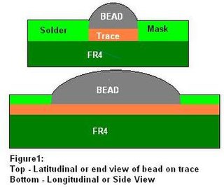
Bead probe technology (BPT) is technique used to provide electrical access to printed circuit board (PCB) circuitry for performing in-circuit testing (ICT). It makes use of small beads of solder placed onto the board's traces to allow measuring and controlling of the signals using a test probe. This permits test access to boards on which standard ICT test pads are not feasible due to space constraints.
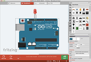
Fritzing is an open-source initiative to develop amateur or hobby CAD software for the design of electronics hardware, intended to allow designers and artists to build more permanent circuits from prototypes. It was developed at the University of Applied Sciences Potsdam. Fritzing is free software under the GPL 3.0 or later license, with the source code available on GitHub and the binaries at a monetary cost, which is allowed by the GPL.
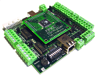
A single-board microcontroller is a microcontroller built onto a single printed circuit board. This board provides all of the circuitry necessary for a useful control task: a microprocessor, I/O circuits, a clock generator, RAM, stored program memory and any necessary support ICs. The intention is that the board is immediately useful to an application developer, without requiring them to spend time and effort to develop controller hardware.
Pad cratering is a mechanically induced fracture in the resin between copper foil and outermost layer of fiberglass of a printed circuit board (PCB). It may be within the resin or at the resin to fiberglass interface.

In microelectronics, a quad in-line package, is an electronic component package with a rectangular housing and four parallel rows of electrical connecting pins. The package may be through-hole mounted to a printed circuit board (PCB) or inserted in a socket. Rockwell used a QIP with 42 leads formed into staggered rows for their PPS-4 microprocessor family introduced in 1973, and other microprocessors and microcontrollers, some with higher lead counts, through the early 1990s.
Onanon is a design, engineering and manufacturing company specializing in the automating panel array manufacturing process, which can produce multiple units in a single session. The company utilizes engineered plastics for manufacturing, using high-speed machinery and automation to produce connectors in large batches. The process removes the need for human handling, thus reducing the probability of error. Onanon utilizes printed circuit boards as a base to add other components. Headquartered in Milpitas, California, Onanon is the first company to introduce a PC board as a connector pin substrate, a technique which is considered standard today but was seen as revolutionary at the time.