The software was created with inspiration from the Processing programming language and the Arduino microcontroller[6] and allows a designer, artist, researcher, or hobbyist to document their Arduino-based prototype and create a PCB layout for manufacturing. The associated website helps users share and discuss drafts and experiences as well as to reduce manufacturing costs.
Fritzing can be seen as an electronic design automation (EDA) tool for non-engineers: the input metaphor is inspired by the environment of designers (the breadboard-based prototype), while the output is focused on accessible means of production. As of December 2, 2014 Fritzing has made a code view option, where one can modify code and upload it directly to an Arduino device.[7]
Component images are distributed under CC BY-SA 3.0, which will also be the license for any generated breadboard views.
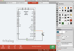
Breadboard view of a simple circuit, drawn with Fritzing.
Circuit diagram of the same circuit.
Other services
Fritzing Creator Kit
The "Fritzing Creator Kit" is available for purchase in the website's online shop. It is a set of various electronic components, including an Arduino UNO board depending on the model, and a book explaining various experiments that can be conducted using the kit. The Fritzing Creator Kit is currently available in English and German. The set is aimed primarily at young people aged 12 and older, who are encouraged to immerse themselves in the world of electronics with the help of the Fritzing Creator Kit.[8][9]
Fritzing Fab
Fritzing allows for creation of PCBs. Fritzing provides access to a commercial service known as 'FritzingFab' to order PCBs created with designs made on the Fritzing software.
2016-2019 Fritzing Development Stall
From 2016-2019, development for version 0.9.4 stopped, mainly because Fritzing's revenue declined.[10] Before 2016, when Fritzing 0.9.3b was released, donations were not mandatory,[citation needed] so only a few users who downloaded Fritzing donated. Some users wanted development to continue.[citation needed]
Finally, in 2019, Aisler arranged a development team for Fritzing,[11] started an initiative to find a Maintainer for Fritzing, to which Kjell Morgenstern responded,[12] and version 0.9.4 was released. Since then, donations were compulsory, with options to donate either 8€ or 25€.[13]
Simulator
Breadboard view of an LED (Simulated with Fritzing's Simulator on v0.9.10)555 IC Astable Circuit (Simulated with the Transitory Simulator on v1.0.5)
Since version 0.9.10, Fritzing incorporates a basic simulator,[14] which became non-beta in version 1.0.0. The main aim of the simulator is to teach electronics to beginners, and Fritzing version 0.9.10 only supports analysis of DC circuits. The simulator works on the breadboard and schematic views. In addition, it checks that the parts are working within their specifications (otherwise, a smoke symbol appears). The simulator provides multimeters to read voltages and currents and it attempts to recreate a realistic laboratory session.
The simulator was officially supported in Fritzing 1.0.0, and improvements have been made since.
Transient mode for simulation (or Transitory Simulation) was also released,[when?] but it is still a beta feature and is only enabled for Fritzing in debug mode.
Friends of Fritzing e.V.
Friends of Fritzing e.V. Batch
Friends of Fritzing e.V. was a non-profit association established in 2012 to support the development and sustainability of the Fritzing project. Fritzing itself began in 2007 as a publicly funded research initiative at the University of Applied Sciences Potsdam, Germany, and later transitioned to community-driven development.
The foundation played a crucial role in maintaining the Fritzing software and its ecosystem. However, due to administrative overhead, Friends of Fritzing e.V. ceased operations in 2018.
Following the closure, the Fritzing team sought alternative methods to sustain the project. Kjell Morgenstern proposed having initiatives like the support for payments by FlatHub, or even a SnapStore with micropayments.[15] In the end, the team transitioned to Open Collective[16]
Bendable legs for many parts in breadboard view, bezier curves for wires and bendable legs in breadboard view, more intelligent connection handling when swapping dissimilar parts, easier to select small traces in pcb view, more extensive cursor feedback, wider range of LED colors, new parts, moved some options from the View menu to Preferences, bug fixes around Gerber export
↑publicly distributed via Linux distros (e.g. Ubuntu), not formally announced by the Fritzing team.
↑Note: A bugfix update to 0.7.5, despite having the "b" which usually implies "beta". In this case, it represents a post-release patch rather than a pre-release.
↑By Kjell Morgenstern: "For Fritzing, the advantage is the direct contact with users. Lots of users. Fritzing is used by teachers and students, makers, curious people, professionals who majored in other disciplines than electronics. This is why an 8 Euro service fee works." https://forum.fritzing.org/t/can-t-find-source-code/19723/7
This page is based on this Wikipedia article Text is available under the CC BY-SA 4.0 license; additional terms may apply. Images, videos and audio are available under their respective licenses.