Computer-aided design (CAD) is the use of computers (or workstations) to aid in the creation, modification, analysis, or optimization of a design.[1]:3 This software is used to increase the productivity of the designer, improve the quality of design, improve communications through documentation, and to create a database for manufacturing.[1]:4 Designs made through CAD software help protect products and inventions when used in patent applications. CAD output is often in the form of electronic files for print, machining, or other manufacturing operations. The terms computer-aided drafting (CAD) and computer-aided design and drafting (CADD) are also used.[2]
CAD software for mechanical design uses either vector-based graphics to depict the objects of traditional drafting, or may also produce raster graphics showing the overall appearance of designed objects. However, it involves more than just shapes. As in the manual drafting of technical and engineering drawings, the output of CAD must convey information, such as materials, processes, dimensions, and tolerances, according to application-specific conventions.
The design of geometric models for object shapes, in particular, is occasionally called computer-aided geometric design (CAGD).[7]
Overview
Computer-aided design is one of the many tools used by engineers and designers and is used in many ways depending on the profession of the user and the type of software in question.
CAD is one part of the whole digital product development (DPD) activity within the product lifecycle management (PLM) processes, and as such is used together with other tools, which are either integrated modules or stand-alone products, such as:
CAD is also used for the accurate creation of photo simulations that are often required in the preparation of environmental impact reports, in which computer-aided designs of intended buildings are superimposed into photographs of existing environments to represent what that locale will be like, where the proposed facilities are allowed to be built. Potential blockage of view corridors and shadow studies are also frequently analyzed through the use of CAD.[8]
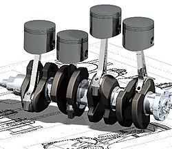
A simple procedure of recreating a solid model out of 2D sketches
There are several different types of CAD,[9] each requiring the operator to think differently about how to use them and design their virtual components in a different manner. Virtually all of CAD tools rely on constraint concepts that are used to define geometric or non-geometric elements of a model.
2D CAD
There are many producers of the lower-end 2D sketching systems, including a number of free and open-source programs. These provide an approach to the drawing process where scale and placement on the drawing sheet can easily be adjusted in the final draft as required, unlike in hand drafting.
3D CAD
3D wireframe is an extension of 2D drafting into a three-dimensional space. Each line has to be manually inserted into the drawing. The final product has no mass properties associated with it and cannot have features directly added to it, such as holes. The operator approaches these in a similar fashion to the 2D systems, although many 3D systems allow using the wireframe model to make the final engineering drawing views.
3D "dumb" solids are created in a way analogous to manipulations of real-world objects. Basic three-dimensional geometric forms (e.g., prisms, cylinders, spheres, or rectangles) have solid volumes added or subtracted from them as if assembling or cutting real-world objects. Two-dimensional projected views can easily be generated from the models. Basic 3D solids do not usually include tools to easily allow the motion of the components, set their limits to their motion, or identify interference between components.
Parametric modeling allows the operator to use what is referred to as "design intent". The objects and features are created modifiable. Any future modifications can be made by changing on how the original part was created. If a feature was intended to be located from the center of the part, the operator should locate it from the center of the model. The feature could be located using any geometric object already available in the part, but this random placement would defeat the design intent. If the operator designs the part as it functions, the parametric modeler is able to make changes to the part while maintaining geometric and functional relationships.
Direct or explicit modeling provide the ability to edit geometry without a history tree. With direct modeling, once a sketch is used to create geometry it is incorporated into the new geometry, and the designer only has to modify the geometry afterward without needing the original sketch. As with parametric modeling, direct modeling has the ability to include the relationships between selected geometry (e.g., tangency, concentricity).
Assembly modelling is a process which incorporates results of the previous single-part modelling into a final product containing several parts. Assemblies can be hierarchical, depending on the specific CAD software vendor, and highly complex models can be achieved (e.g. in building engineering by using computer-aided architectural design software)[10]:539
Top-end CAD systems offer the capability to incorporate more organic, aesthetic and ergonomic features into the designs. Freeform surface modeling is often combined with solids to allow the designer to create products that fit the human form and visual requirements as well as they interface with the machine.
Originally software for CAD systems was developed with computer languages such as Fortran, ALGOL but with the advancement of object-oriented programming methods this has radically changed. Typical modern parametric feature-based modeler and freeform surface systems are built around a number of key C modules with their own APIs. A CAD system can be seen as built up from the interaction of a graphical user interface (GUI) with NURBS geometry or boundary representation (B-rep) data via a geometric modeling kernel. A geometry constraint engine may also be employed to manage the associative relationships between geometry, such as wireframe geometry in a sketch or components in an assembly.
Unexpected capabilities of these associative relationships have led to a new form of prototyping called digital prototyping. In contrast to physical prototypes, which entail manufacturing time in the design. That said, CAD models can be generated by a computer after the physical prototype has been scanned using an industrial CT scanning machine. Depending on the nature of the business, digital or physical prototypes can be initially chosen according to specific needs.
Today, CAD systems exist for all the major platforms (Windows, Linux, UNIX and Mac OS X); some packages support multiple platforms.[11]
Currently, no special hardware is required for most CAD software. However, some CAD systems can do graphically and computationally intensive tasks, so a modern graphics card, high speed (and possibly multiple) CPUs and large amounts of RAM may be recommended.
The human-machine interface is generally via a computer mouse but can also be via a pen and digitizing graphics tablet. Manipulation of the view of the model on the screen is also sometimes done with the use of a Spacemouse/SpaceBall. Some systems also support stereoscopic glasses for viewing the 3D model. Technologies that in the past were limited to larger installations or specialist applications have become available to a wide group of users. These include the CAVE or HMDs and interactive devices like motion-sensing technology.
Starting with the IBM Drafting System in the mid-1960s, computer-aided design systems began to provide more capabilities than just an ability to reproduce manual drafting with electronic drafting, and the cost-benefit for companies to switch to CAD became apparent. The software automated many tasks that are taken for granted from computer systems today, such as automated generation of bills of materials, auto layout in integrated circuits, interference checking, and many others. Eventually, CAD provided the designer with the ability to perform engineering calculations.[5] During this transition, calculations were still performed either by hand or by those individuals who could run computer programs. CAD was a revolutionary change in the engineering industry, where draftsman, designer, and engineer roles that had previously been separate began to merge. CAD is an example of the pervasive effect computers were beginning to have on the industry. Current computer-aided design software packages range from 2D vector-based drafting systems to 3D solid and surface modelers. Modern CAD packages can also frequently allow rotations in three dimensions, allowing viewing of a designed object from any desired angle, even from the inside looking out.[5] Some CAD software is capable of dynamic mathematical modeling.[5]
CAD technology is used in the design of tools and machinery and in the drafting and design of all types of buildings, from small residential types (houses) to the largest commercial and industrial structures (hospitals and factories).[12]
CAD is mainly used for detailed design of 3D models or 2D drawings of physical components, but it is also used throughout the engineering process from conceptual design and layout of products, through strength and dynamic analysis of assemblies to definition of manufacturing methods of components. It can also be used to design objects such as jewelry, furniture, appliances, etc. Furthermore, many CAD applications now offer advanced rendering and animation capabilities so engineers can better visualize their product designs. 4D BIM is a type of virtual construction engineering simulation incorporating time or schedule-related information for project management.
CAD has become an especially important technology within the scope of computer-aided technologies, with benefits such as lower product development costs and a greatly shortened design cycle. CAD enables designers to layout and develop work on screen, print it out and save it for future editing, saving time on their drawings.
License management software
In the 2000s, some CAD system software vendors shipped their distributions with a dedicated license manager software that controlled how often or how many users can utilize the CAD system.[5]:166 It could run either on a local machine (by loading from a local storage device) or a local network fileserver and was usually tied to a specific IP address in latter case.[5]:166
3D computer graphics– Graphics that use a three-dimensional representation of geometric data
3D printing– Additive process used to make a 3D object
Additive Manufacturing File Format– Open standard for describing objects for additive manufacturing processes such as 3D printingPages displaying short descriptions of redirect targets
123456Schoonmaker, Stephen J. (2003). The CAD guidebook: a basic manual for understanding and improving computer-aided design. New York: Marcel Dekker. ISBN0-8247-0871-7. OCLC50868192.
This page is based on this Wikipedia article Text is available under the CC BY-SA 4.0 license; additional terms may apply. Images, videos and audio are available under their respective licenses.