Technical drawing, drafting or drawing, is the act and discipline of composing drawings that visually communicate how something functions or is constructed.
The need for precise communication in the preparation of a functional document distinguishes technical drawing from the expressive drawing of the visual arts. Artistic drawings are subjectively interpreted; their meanings are multiply determined. Technical drawings are understood to have one intended meaning.[1]
A draftsman is a person who makes a drawing (technical or expressive). A professional drafter who makes technical drawings is sometimes called a drafting technician.
A sketch is a quickly executed, freehand drawing that is usually not intended as a finished work. In general, sketching is a quick way to record an idea for later use. Architect's sketches primarily serve as a way to try out different ideas and establish a composition before a more finished work, especially when the finished work is expensive and time-consuming.
Architectural sketches, for example, are a kind of diagram.[2] These sketches, like metaphors, are used by architects as a means of communication in aiding design collaboration. This tool helps architects to abstract attributes of hypothetical provisional design solutions and summarize their complex patterns, thereby enhancing the design process.[2]
Manual or by instrument
A drafting tableOld-fashioned technical drawing instrumentsStencils for lettering technical drawings to DIN standards
The basic drafting procedure is to place a piece of paper (or other material) on a smooth surface with right-angle corners and straight sides—typically a drawing board. A sliding straightedge known as a T-square is then placed on one of the sides, allowing it to be slid across the side of the table, and over the surface of the paper.
"Parallel lines" can be drawn by moving the T-square and running a pencil or technical pen along the T-square's edge. The T-square is used to hold other devices such as set squares or triangles. In this case, the drafter places one or more triangles of known angles on the T-square — which is itself at right angles to the edge of the table — and can then draw lines at any chosen angle to others on the page. Modern drafting tables are equipped with a drafting machine that is supported on both sides of the table to slide over a large piece of paper. Because it is secured on both sides, lines drawn along the edge are guaranteed to be parallel.[3]
The drafter uses several technical drawing tools to draw curves and circles. Primary among these are the compasses, used for drawing arcs and circles, and the French curve, for drawing curves. A spline is a rubber coated articulated metal that can be manually bent to most curves.
Drafting templates assist the drafter with creating recurring objects in a drawing without having to reproduce the object from scratch every time. This is especially useful when using common symbols; i.e. in the context of stagecraft, a lighting designer will draw from the USITT standard library of lighting fixture symbols to indicate the position of a common fixture across multiple positions. Templates are sold commercially by a number of vendors, usually customized to a specific task, but it is also not uncommon for a drafter to create his own templates.
This basic drafting system requires an accurate table and constant attention to the positioning of the tools. Even tasks as simple as drawing two angled lines meeting at a point require a number of moves of the T-square and triangles, and in general, drafting can be a time-consuming process.
A solution to these problems was the introduction of the mechanical "drafting machine", an application of the pantograph (sometimes referred to incorrectly as a "pentagraph" in these situations) which allowed the drafter to have an accurate right angle at any point on the page quickly. These machines often included the ability to change the angle, hence removing the need for the triangles.
In addition to the mastery of the mechanics of drawing lines, arcs and circles (and text) onto a piece of paper—with respect to the detailing of physical objects—the drafting effort requires a thorough understanding of geometry, trigonometry and spatial comprehension, and in all cases demands precision and accuracy, and attention to detail of high order.
Although drafting is sometimes accomplished by a project engineer, architect, or shop personnel (such as a machinist), skilled drafters (or designers) usually accomplish the task, and are always in demand to some degree.
2D CAD systems such as AutoCAD or MicroStation replace the paper drawing discipline. The lines, circles, arcs, and curves are created within the software. It is down to the technical drawing skill of the user to produce the drawing. There is still much scope for error in the drawing when producing first and third angle orthographic projections, auxiliary projections and cross-section views. A 2D CAD system is merely an electronic drawing board. Its greatest strength over direct to paper technical drawing is in the making of revisions. Whereas in a conventional hand drawn technical drawing, if a mistake is found, or a modification is required, a new drawing must be made from scratch, the 2D CAD system allows a copy of the original to be modified, saving considerable time. 2D CAD systems can be used to create plans for large projects such as buildings and aircraft but provide no way to check the various components will fit together.
A 3D CAD system (such as KeyCreator, Autodesk Inventor, or SolidWorks) first produces the geometry of the part; the technical drawing comes from user defined views of that geometry. Any orthographic, projected or sectioned view is created by the software. There is no scope for error in the production of these views. The main scope for error comes in setting the parameter of first or third angle projection and displaying the relevant symbol on the technical drawing. 3D CAD allows individual parts to be assembled together to represent the final product. Buildings, aircraft, ships, and cars are modelled, assembled, and checked in 3D before technical drawings are released for manufacture.
Both 2D and 3D CAD systems can be used to produce technical drawings for any discipline. The various disciplines (electrical, electronic, pneumatic, hydraulic, etc.) have industry recognized symbols to represent common components.
BS and ISO produce standards to show recommended practices but it is up to individuals to produce the drawings to a standard. There is no definitive standard for layout or style. The only standard across engineering workshop drawings is in the creation of orthographic projections and cross-section views.
In representing complex, three-dimensional objects in two-dimensional drawings, the objects can be described by at least one view plus material thickness notes and as many views and sections that are required to show all features of an object.
The art and design that goes into making buildings is known as architecture. To communicate all aspects of the shape or design, detail drawings are used. In this field, the term plan is often used when referring to the full section view of these drawings as viewed from three feet above finished floor to show the locations of doorways, windows, stairwells, etc.[4] Architectural drawings describe and document an architect's design.[5]
Engineering can be a very broad term. It stems from the Latin ingenerare, meaning "to create".[6] Because this could apply to everything that humans create, it is given a narrower definition in the context of technical drawing. Engineering drawings generally deal with mechanical engineered items, such as manufactured parts and equipment.
Engineering drawings are usually created in accordance with standardized conventions for layout, nomenclature, interpretation, appearance (such as typefaces and line styles), size, etc.
Its purpose is to accurately and unambiguously capture all the geometric features of a product or a component. The end goal of an engineering drawing is to convey all the required information that will allow a manufacturer to produce that component.
Practitioners reported that diagramming helped with analysing requirements,[7]:539 design, refactoring, documentation, onboarding, communication with stake holders.[8]:560 Diagrams are often transient or redrawn as required. Redrawn diagrams can act as a form of shared understanding in a team.[8]:561
Technical illustration is the use of illustration to visually communicate information of a technical nature. Technical illustrations can be component technical drawings or diagrams. The aim of technical illustration is "to generate expressive images that effectively convey certain information via the visual channel to the human observer".[9]
The main purpose of technical illustration is to describe or explain these items to a more or less nontechnical audience. The visual image should be accurate in terms of dimensions and proportions, and should provide "an overall impression of what an object is or does, to enhance the viewer's interest and understanding".[10]
According to Viola (2005), "illustrative techniques are often designed in a way that even a person with no technical understanding clearly understands the piece of art. The use of varying line widths to emphasize mass, proximity, and scale helped to make a simple line drawing more understandable to the lay person. Cross hatching, stippling, and other low abstraction techniques gave greater depth and dimension to the subject matter".[9]
A cutaway drawing is a technical illustration, in which part of the surface of a three-dimensional model is removed in order to show some of the model's interior in relation to its exterior.
The purpose of a cutaway drawing is to "allow the viewer to have a look into an otherwise solid opaque object. Instead of letting the inner object shine through the surrounding surface, parts of outside object are simply removed. This produces a visual appearance as if someone had cutout a piece of the object or sliced it into parts. Cutaway illustrations avoid ambiguities with respect to spatial ordering, provide a sharp contrast between foreground and background objects, and facilitate a good understanding of spatial ordering".[11]
Technical drawings
Types
The two types of technical drawings are based on graphical projection.[1] This is used to create an image of a three-dimensional object onto a two-dimensional surface.
Two-dimensional representation
Two-dimensional representation uses orthographic projection to create an image where only two of the three dimensions of the object are seen.
Three-dimensional representation
In a three-dimensional representation, also referred to as a pictorial, all three dimensions of an object are visible.
Multiview is a type of orthographic projection. There are two conventions for using multiview, first-angle and third-angle. In both cases, the front or main side of the object is the same. First-angle is drawing the object sides based on where they land. Example, looking at the front side, rotate the object 90degrees to the right. What is seen will be drawn to the right of the front side. Third-angle is drawing the object sides based on where they are. Example, looking at the front side, rotate the object 90degrees to the right. What is seen is actually the left side of the object and will be drawn to the left of the front side.
Section
While multiview relates to external surfaces of an object, section views show an imaginary plane cut through an object. This is often useful to show voids in an object.
Auxiliary
Auxiliary views utilize an additional projection plane other than the common planes in a multiview. Since the features of an object need to show the true shape and size of the object, the projection plane must be parallel to the object surface. Therefore, any surface that is not in line with the three major axis needs its own projection plane to show the features correctly.
Patterns, sometimes called developments, show the size and shape of a flat piece of material needed for later bending or folding into a three-dimensional shape.[12]
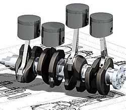
An exploded-view drawing is a technical drawing of an object that shows the relationship or order of assembly of the various parts.[13] It shows the components of an object slightly separated by distance or suspended in surrounding space in the case of a three-dimensional exploded diagram. An object is represented as if there had been a small controlled explosion emanating from the middle of the object, causing the object's parts to be separated relative distances away from their original locations.
An exploded view drawing (EVD) can show the intended assembly of mechanical or other parts. In mechanical systems, the component closest to the center is usually assembled first or is the main part inside which the other parts are assembled. The EVD can also help to represent the disassembly of parts, where those on the outside are normally removed first.[14]
There have been many standard sizes of paper at different times and in different countries, but today most of the world uses the international standard (A4 and its siblings). North America uses its own sizes.
ISO A-series paper sizes, used in most countries of the world
The applicant for a patent will be required by law to furnish a drawing of the invention if or when the nature of the case requires a drawing to understand the invention with the job. This drawing must be filed with the application. This includes practically all inventions except compositions of matter or processes, but a drawing may also be useful in the case of many processes.[13]
The drawing must show every feature of the invention specified in the claims and is required by the patent office rules to be in a particular form. The Office specifies the size of the sheet on which the drawing is made, the type of paper, the margins, and other details relating to the making of the drawing. The reason for specifying the standards in detail is that the drawings are printed and published in a uniform style when the patent issues and the drawings must also be such that they can be readily understood by people using the patent descriptions.[13]
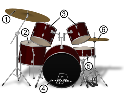
Assembly drawings show how different parts go together, identify those parts by number, and have a parts list, often referred to as a bill of materials.[16] In a technical service manual, this type of drawing may be referred to as an exploded view drawing or diagram. These parts may be used in engineering.
As-fitted drawings
Also called as-built and as-made, an as-fitted drawing represents a record of a completed work, literally as fitted. An as-fitted drawing is based upon working drawings and updated to reflect any changes during construction or manufacture.[17]
1 2 Goetsch, David L.; Chalk, William S.; Nelson, John A. (2000). Technical Drawing. Delmar Technical Graphics Series (Fourthed.). Albany: Delmar Learning. p.3. ISBN978-0-7668-0531-6. OCLC39756434.
1 2 Richard Boland and Fred Collopy (2004). Managing as designing. Stanford University Press, 2004. ISBN0-8047-4674-5, p.69.
↑ Lieu, Dennis K; Sorby, Sheryl (2009), Visualization, Modeling, and Graphics for Engineering Design (1st ed.), Clifton Park, NY: Delmar Cengage Learning, ISBN978-1-4018-4249-9, pp. 1–2
1 2 Ivan Viola and Meister E. Gröller (2005). "Smart Visibility in Visualization". In: Computational Aesthetics in Graphics, Visualization and Imaging. L. Neumann et al. (Ed.)
↑ Diepstraten, J.; Weiskopf, D.; Ertl, T. (2003). "Interactive Cutaway Illustrations"(PDF). vis.uni-stuttgart.de. Archived from the original(PDF) on 16 December 2005. in Brunet, P.; Fellner, D. (eds.). "Eurographics 2003". Eurographics. 22 (3). The Eurographics Association and Blackwell Publishers.
Wolfgang Lefèvre ed. (2004). Picturing Machines 1400–1700: How technical drawings shaped early engineering practice. MIT Press, 2004. ISBN0-262-12269-3
This page is based on this Wikipedia article Text is available under the CC BY-SA 4.0 license; additional terms may apply. Images, videos and audio are available under their respective licenses.