Drawing board

Last updated
A 19th century architect at the drawing board Architect.png
A 19th century architect at the drawing board

A drawing board (also drawing table, drafting table or architect's table) is, in its antique form, a kind of multipurpose desk which can be used for any kind of drawing, writing or impromptu sketching on a large sheet of paper or for reading a large format book or other oversized document or for drafting precise technical illustrations (such as engineering drawings or architectural drawings). The drawing table used to be a frequent companion to a pedestal desk in a study or private library, during the pre-industrial and early industrial era.

Contents

During the Industrial Revolution, draftsmanship gradually became a specialized trade and drawing tables slowly moved out of the libraries and offices of most gentlemen. They became more utilitarian and were built of steel and plastic instead of fine woods and brass.

More recently, engineers and draftsmen use the drawing board for making and modifying drawings on paper with ink or pencil. Different drawing instruments (set square, protractor, etc.) are used on it to draw parallel, perpendicular or oblique lines. There are instruments for drawing circles, arcs, other curves and symbols too (compass, French curve, stencil, etc.). However, with the gradual introduction of computer aided drafting and design (CADD or CAD) in the last decades of the 20th century and the first of the 21st century, the drawing board is becoming less common.

A drawing table is also sometimes called a mechanical desk because, for several centuries, most mechanical desks were drawing tables. Unlike the gadgety mechanical desks of the second part of the 18th century, however, the mechanical parts of drawing tables were usually limited to notches, ratchets, and perhaps a few simple gears, or levers or cogs to elevate and incline the working surface.

Very often a drawing table could look like a writing table or even a pedestal desk when the working surface was set at the horizontal and the height adjusted to 29 inches, in order to use it as a "normal" desk. The only giveaway was usually a lip on one of the sides of the desktop. This lip or edge stopped paper or books from sliding when the surface was given an angle. It was also sometimes used to hold writing implements. When the working surface was extended at its full height, a drawing table could be used as a standing desk.

Many reproductions have been made and are still being produced of drawing tables, copying the period styles they were originally made in during the 18th and 19th centuries.

History

In the 18th and 19th centuries, drawing paper was dampened and then its edges glued to the drawing board. After drying the paper would be flat and smooth. The completed drawing was then cut free. [1] : 1-2 Paper could also be secured to the drawing board with drawing pins [2] or even C-clamps. More recent practice is to use self-adhesive drafting tape to secure paper to the board, including the sophisticated use of individualized adhesive dots from a dispensing roll. Some drawing boards are magnetized, allowing paper to be held down by long steel strips. Boards used for overlay drafting or animation may include registration pins or peg bars to ensure alignment of multiple layers of drawing media.

Contemporary drafting tables

A drawing board with drafting machine, eliminating the need for a T-square Zeichenmaschine.jpg
A drawing board with drafting machine, eliminating the need for a T-square

Despite the prevalence of computer aided drafting, many older architects and even some structural designers still rely on paper and pencil graphics produced on a drafting table.

Modern drafting tables typically rely on a steel frame. Steel provides as much strength as the old oak drafting table frames and much easier portability. Typically the drafting board surface is a thick sheet of compressed fibreboard with sheets of Formica laminated to all its surfaces. The drafting board surface is usually secured to the frame by screws which can easily be removed for drafting table transportation.

The steel frame allows mechanical linkages to be installed that control both the height and angle of the drafting board surface. Typically, a single foot pedal is used to control a clutch which clamps the board in the desired position. A heavy counterweight full of lead shot is installed in the steel linkage so that if the pedal is accidentally released, the drafting board will not spring into the upright position and injure the user. Drafting table linkages and clutches have to be maintained to ensure that this safety mechanism counterbalances the weight of the table surface.

A modern drafting table with a parallel motion rule Adjustable Cedar Board Drawing Board side view.jpg
A modern drafting table with a parallel motion rule

The drafting table surface is usually covered with a thin vinyl sheet called a board cover. This provides an optimum surface for pen and pencil drafting. It allows compasses and dividers to be used without damaging the wooden surface of the board. A board cover must be frequently cleaned to prevent graphite buildup from making new drawings dirty. At the bottom edge of the table, a single strip of aluminum or steel may serve as a place to rest drafting pencils. More purpose-built trays are also used which hold pencils even while the board is being adjusted.

Various types of drafting machine may be attached to the board surface to assist the draftsperson or artist. Parallel rules often span the entire width of the board and are so named because they remain parallel to the top edge of the board as they are moved up and down. Drafting machines use pre-calibrated scales and built in protractors to allow accurate drawing measurement.

Some drafting tables incorporate electric motors to provide the up and down and angle adjustment of the drafting table surface. These tables are at least as heavy as the original oak and brass drafting tables and so sacrifice portability for the convenience of push button table adjustment.

Modern-day idiom

The expression "back to the drawing board" is used when a plan or course of action needs to be changed, often drastically; usually due to a very unsuccessful result; e.g., "The battle plan, the result of months of conferences, failed because the enemy retreated too far back. It was back to the drawing board for the army captains."

The phrase was coined in the caption to a Peter Arno cartoon of The New Yorker of March 1, 1941. [3]

See also

Related Research Articles

<span class="mw-page-title-main">Drawing</span> Visual artwork on two-dimensional surface

Drawing is a visual art that uses an instrument to mark paper or another two-dimensional surface. The instruments used to make a drawing are pencils, crayons, pens with inks, brushes with paints, or combinations of these, and in more modern times, computer styluses with graphics tablets or gamepads in VR drawing software.

<span class="mw-page-title-main">Technical drawing</span> Creation of standards and the technical drawings

Technical drawing, drafting or drawing, is the act and discipline of composing drawings that visually communicate how something functions or is constructed.

<span class="mw-page-title-main">Engineering drawing</span> Type of technical drawing used to define requirements for engineered items

An engineering drawing is a type of technical drawing that is used to convey information about an object. A common use is to specify the geometry necessary for the construction of a component and is called a detail drawing. Usually, a number of drawings are necessary to completely specify even a simple component. These drawings are linked together by a "master drawing." This "master drawing" is more commonly known as an assembly drawing. The assembly drawing gives the drawing numbers of the subsequent detailed components, quantities required, construction materials and possibly 3D images that can be used to locate individual items. Although mostly consisting of pictographic representations, abbreviations and symbols are used for brevity and additional textual explanations may also be provided to convey the necessary information.

<span class="mw-page-title-main">Stationery</span> Writing materials

Stationery refers to commercially manufactured writing materials, including cut paper, envelopes, writing implements, continuous form paper, and other office supplies. Stationery includes materials to be written on by hand or by equipment such as computer printers.
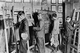
<span class="mw-page-title-main">Easel</span> Upright supporting frame used for displaying and/or fixing something resting upon it

An easel is an upright support used for displaying and/or fixing something resting upon it, at an angle of about 20° to the vertical. In particular, painters traditionally use an easel to support a painting while they work on it, normally standing up; easels are also sometimes used to display finished paintings. Artists' easels are still typically made of wood, in functional designs that have changed little for centuries, or even millennia, though new materials and designs exist. Easels are typically made from wood, aluminum or steel.
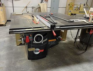
<span class="mw-page-title-main">Table saw</span> Woodworking tool

A table saw is a woodworking tool, consisting of a circular saw blade, mounted on an arbor, that is driven by an electric motor. The drive mechanism is mounted below a table that provides support for the material, usually wood, being cut, with the blade protruding up through the table into the material.

<span class="mw-page-title-main">Whiteboard</span> Surface for nonpermanent markings

A whiteboard is a glossy, usually white surface for making non-permanent markings. Whiteboards are analogous to blackboards, but with a smoother surface allowing for rapid marking and erasing of markings on their surface. The popularity of whiteboards increased rapidly in the mid-1990s and they have become a fixture in many offices, meeting rooms, school classrooms, public events and other work environments.
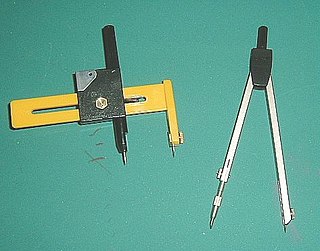
<span class="mw-page-title-main">Compass (drawing tool)</span> Drafting instrument

A compass, more accurately known as a pair of compasses, is a technical drawing instrument that can be used for inscribing circles or arcs. As dividers, it can also be used as a tool to mark out distances, in particular, on maps. Compasses can be used for mathematics, drafting, navigation and other purposes.

A penciller is an artist who works on the creation of comic books, graphic novels, and similar visual art forms, with a focus on the initial pencil illustrations, usually in collaboration with other artists, who provide inks, colors and lettering in the book, under the supervision of an editor.

<span class="mw-page-title-main">Combination square</span> Measuring and marking tool

A combination square is a multi-purpose measuring and marking tool used in metalworking, woodworking, and stonemasonry. It is composed of a rule and one or more interchangeable heads that can be attached to the rule. Other names for the tool include adjustable square, combo square, and sliding square.

A die is a specialized machine tool used in manufacturing industries to cut and/or form material to a desired shape or profile. Stamping dies are used with a press, as opposed to drawing dies and casting dies which are not. Like molds, dies are generally customized to the item they are used to create.
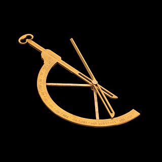
<span class="mw-page-title-main">Goniometer</span> Angle measuring instrument

A goniometer is an instrument that either measures an angle or allows an object to be rotated to a precise angular position. The term goniometry derives from two Greek words, γωνία (gōnía) 'angle' and μέτρον (métron) 'measure'. The protractor is a commonly used type in the fields of mechanics, engineering, and geometry.

<span class="mw-page-title-main">Scriber</span> Hand tool for making marks on workpieces

A scriber is a hand tool used in metal work to mark lines on workpieces, prior to machining. The process of using a scriber is called scribing and is just part of the process of marking out. It is used instead of pencils or ink lines, because the latter are hard to see, easily erased, and imprecise due to their wide mark; scribe lines are thin and semi-permanent. On non-coated workpieces marking blue is commonly used to increase the contrast of the mark lines.

<span class="mw-page-title-main">Vise</span> Apparatus for securing a workpiece

A vise or vice is a mechanical apparatus used to secure an object to allow work to be performed on it. Vises have two parallel jaws, one fixed and the other movable, threaded in and out by a screw and lever. The jaws are often flat but may have grooves, adapt to the shape of the workpiece or be custom made.

<span class="mw-page-title-main">Technical pen</span> Writing implement designed to make lines of constant width

A technical pen is a specialized instrument used by an engineer, architect, or drafter to make lines of constant width for architectural, engineering, or technical drawings. Technical pens may use either a refillable ink reservoir or a replaceable ink cartridge.

<span class="mw-page-title-main">Countertop</span> Horizontal work surface

A countertop, also counter top, counter, benchtop, worktop or kitchen bench, bunker is a raised, firm, flat, and horizontal surface. They are built for work in kitchens or other food preparation areas, bathrooms or lavatories, and workrooms in general. The surface is frequently installed upon and supported by cabinets, positioned at an ergonomic height for the user and the particular task for which it is designed. A countertop may be constructed of various materials with different attributes of functionality, durability and aesthetics, and may have built-in appliances, or accessory items relative to the intended application.

This glossary of woodworking lists a number of specialized terms and concepts used in woodworking, carpentry, and related disciplines.

<span class="mw-page-title-main">Drafter</span> Person who makes technical drawings

A drafter is an engineering technician who makes detailed technical drawings or plans for machinery, buildings, electronics, infrastructure, sections, etc. Drafters use computer software and manual sketches to convert the designs, plans, and layouts of engineers and architects into a set of technical drawings. Drafters operate as the supporting developers and sketch engineering designs and drawings from preliminary design concepts.

<span class="mw-page-title-main">Technical drawing tool</span> Tools and instruments used for accurate and precise manual drafting

Drafting tools may be used for measurement and layout of drawings, or to improve the consistency and speed of creation of standard drawing elements. Tools such as pens and pencils mark the drawing medium. Other tools such as straight edges, assist the operator in drawing straight lines, or assist the operator in drawing complicated shapes repeatedly. Various scales and the protractor are used to measure the lengths of lines and angles, allowing accurate scale drawing to be carried out. The compass is used to draw arcs and circles. A drawing board was used to hold the drawing media in place; later boards included drafting machines that sped the layout of straight lines and angles. Tools such as templates and lettering guides assisted in the drawing of repetitive elements such as circles, ellipses, schematic symbols and text. Other auxiliary tools were used for special drawing purposes or for functions related to the preparation and revision of drawings. The tools used for manual technical drawing have been displaced by the advent of computer-aided drawing, drafting and design (CADD).
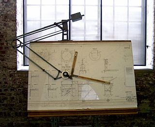
<span class="mw-page-title-main">Drafting machine</span> Tool for technical drawing

A drafting machine is a tool used in technical drawing, consisting of a pair of scales mounted to form a right angle on an articulated protractor head that allows an angular rotation.

References

  1. Heather, John Fry (1884). Mathematical Instruments: Their Construction, Adjustment, Testing and Use: Comprising Drawing, Measuring, Optical, Surveying, and Astronomical Instruments . Weale's scientific & technical series. Crosby, Lockwood and Co. pp. 1–2. ISBN   978-0344280559. LCCN   05025600. OCLC   222119838. OL   32907144M via Internet Archive.
  2. The American engineer Volumes 19–20, 1890 page 107
  3. Image goodcomics.comicbookresources.com August 2009 Archived 2011-01-31 at the Wayback Machine