Database design

Last updated

Database design is the organization of data according to a database model. The designer determines what data must be stored and how the data elements interrelate. With this information, they can begin to fit the data to the database model. [1] A database management system manages the data accordingly.

Contents

Database design is a process that consists in several steps.

Conceptual data modeling

The first step of database design involves classifying data and identifying interrelationships. This theoretical representation of the data is called an ontology or a conceptual data model .

Determining data to be stored

In a majority of cases, a person who is doing the design of a database is a person with expertise in the area of database design, rather than expertise in the domain from which the data to be stored is drawn e.g. financial information, biological information etc. Therefore, the data to be stored in the database must be determined in cooperation with a person who does have expertise in that domain, and who is aware of what data must be stored within the system.

This process is one which is generally considered part of requirements analysis, and requires skill on the part of the database designer to elicit the needed information from those with the domain knowledge. This is because those with the necessary domain knowledge often cannot clearly express the system requirements for the database as they are unaccustomed to thinking in terms of the discrete data elements which must be stored. Data to be stored can be determined by Requirement Specification. [2]

Determining data relationships

Once a database designer is aware of the data which is to be stored within the database, they must then determine where dependency is within the data. Sometimes when data is changed you can be changing other data that is not visible. For example, in a list of names and addresses, assuming a situation where multiple people can have the same address, but one person cannot have more than one address, the address is dependent upon the name. When provided a name and the list the address can be uniquely determined; however, the inverse does not hold – when given an address and the list, a name cannot be uniquely determined because multiple people can reside at an address. Because an address is determined by a name, an address is considered dependent on a name.

(NOTE: A common misconception is that the relational model is so called because of the stating of relationships between data elements therein. This is not true. The relational model is so named because it is based upon the mathematical structures known as relations.)

Conceptual schema

The information obtained can be formalized in a diagram or schema. At this stage, it is a conceptual schema.

ER diagram (entity–relationship model)
A sample entity-relationship diagram ER Diagram MMORPG.png
A sample entity–relationship diagram

One of the most common types of conceptual schemas is the ER (entity–relationship model) diagrams.

Attributes in ER diagrams are usually modeled as an oval with the name of the attribute, linked to the entity or relationship that contains the attribute.

ER models are commonly used in information system design; for example, they are used to describe information requirements and / or the types of information to be stored in the database during the conceptual structure design phase. [3]

Logical data modeling

Once the relationships and dependencies amongst the various pieces of information have been determined, it is possible to arrange the data into a logical structure which can then be mapped into the storage objects supported by the database management system. In the case of relational databases the storage objects are tables which store data in rows and columns. In an Object database the storage objects correspond directly to the objects used by the Object-oriented programming language used to write the applications that will manage and access the data. The relationships may be defined as attributes of the object classes involved or as methods that operate on the object classes.

The way this mapping is generally performed is such that each set of related data which depends upon a single object, whether real or abstract, is placed in a table. Relationships between these dependent objects are then stored as links between the various objects.

Each table may represent an implementation of either a logical object or a relationship joining one or more instances of one or more logical objects. Relationships between tables may then be stored as links connecting child tables with parents. Since complex logical relationships are themselves tables they will probably have links to more than one parent.

Normalization

In the field of relational database design, normalization is a systematic way of ensuring that a database structure is suitable for general-purpose querying and free of certain undesirable characteristics—insertion, update, and deletion anomalies that could lead to loss of data integrity.

A standard piece of database design guidance is that the designer should create a fully normalized design; selective denormalization can subsequently be performed, but only for performance reasons. The trade-off is storage space vs performance. The more normalized the design is, the less data redundancy there is (and therefore, it takes up less space to store), however, common data retrieval patterns may now need complex joins, merges, and sorts to occur – which takes up more data read, and compute cycles. Some modeling disciplines, such as the dimensional modeling approach to data warehouse design, explicitly recommend non-normalized designs, i.e. designs that in large part do not adhere to 3NF. Normalization consists of normal forms that are 1NF, 2NF, 3NF, Boyce-Codd NF (3.5NF), 4NF, 5NF and 6NF.

Document databases take a different approach. A document that is stored in such a database, typically would contain more than one normalized data unit and often the relationships between the units as well. If all the data units and the relationships in question are often retrieved together, then this approach optimizes the number of retrieves. It also simplifies how data gets replicated, because now there is a clearly identifiable unit of data whose consistency is self-contained. Another consideration is that reading and writing a single document in such databases will require a single transaction – which can be an important consideration in a Microservices architecture. In such situations, often, portions of the document are retrieved from other services via an API and stored locally for efficiency reasons. If the data units were to be split out across the services, then a read (or write) to support a service consumer might require more than one service calls, and this could result in management of multiple transactions, which may not be preferred.

Physical design

Physical data modeling

The physical design of the database specifies the physical configuration of the database on the storage media. This includes detailed specification of data elements and data types.

Other physical design

This step involves specifying the indexing options and other parameters residing in the DBMS data dictionary. It is the detailed design of a system that includes modules & the database's hardware & software specifications of the system. Some aspects that are addressed at the physical layer:

At the application level, other aspects of the physical design can include the need to define stored procedures, or materialized query views, OLAP cubes, etc.

Example: relational database data modeling

The following steps are suggestion of the data modeling process for Microsoft Access, a relational DBMS.

  1. Determine the purpose of the database – This helps prepare for the remaining steps.
  2. Find and organize the information required – Gather all of the types of information to record in the database, such as product name and order number.
  3. Divide the information into tables – Divide information items into major entities or subjects, such as Products or Orders. Each subject then becomes a table.
  4. Turn information items into columns – Decide what information needs to be stored in each table. Each item becomes a field, and is displayed as a column in the table. For example, an Employees table might include fields such as Last Name and Hire Date.
  5. Specify primary keys – Choose each table's primary key. The primary key is a column, or a set of columns, that is used to uniquely identify each row. An example might be Product ID or Order ID.
  6. Set up the table relationships – Look at each table and decide how the data in one table is related to the data in other tables. Add fields to tables or create new tables to clarify the relationships, as necessary.
  7. Refine the design – Analyze the design for errors. Create tables and add a few records of sample data. Check if results come from the tables as expected. Make adjustments to the design, as needed.
  8. Apply the normalization rules – Apply the data normalization rules to see if tables are structured correctly. Make adjustments to the tables, as needed. [4]

See also

Related Research Articles

<span class="mw-page-title-main">Database</span> Organized collection of data in computing

In computing, a database is an organized collection of data or a type of data store based on the use of a database management system (DBMS), the software that interacts with end users, applications, and the database itself to capture and analyze the data. The DBMS additionally encompasses the core facilities provided to administer the database. The sum total of the database, the DBMS and the associated applications can be referred to as a database system. Often the term "database" is also used loosely to refer to any of the DBMS, the database system or an application associated with the database.

A conceptual schema or conceptual data model is a high-level description of informational needs underlying the design of a database. It typically includes only the main concepts and the main relationships among them. Typically this is a first-cut model, with insufficient detail to build an actual database. This level describes the structure of the whole database for a group of users. The conceptual model is also known as the data model that can be used to describe the conceptual schema when a database system is implemented. It hides the internal details of physical storage and targets the description of entities, datatypes, relationships and constraints.

<span class="mw-page-title-main">Data model</span> Model that organizes elements of data and how they relate to one another and to real-world entities.

A data model is an abstract model that organizes elements of data and standardizes how they relate to one another and to the properties of real-world entities. For instance, a data model may specify that the data element representing a car be composed of a number of other elements which, in turn, represent the color and size of the car and define its owner.

<span class="mw-page-title-main">Database schema</span> Visual representation of database system relationships

The database schema is the structure of a database described in a formal language supported typically by a relational database management system (RDBMS). The term "schema" refers to the organization of data as a blueprint of how the database is constructed. The formal definition of a database schema is a set of formulas (sentences) called integrity constraints imposed on a database. These integrity constraints ensure compatibility between parts of the schema. All constraints are expressible in the same language. A database can be considered a structure in realization of the database language. The states of a created conceptual schema are transformed into an explicit mapping, the database schema. This describes how real-world entities are modeled in the database.

<span class="mw-page-title-main">Entity–relationship model</span> Model or diagram describing interrelated things

An entity–relationship model describes interrelated things of interest in a specific domain of knowledge. A basic ER model is composed of entity types and specifies relationships that can exist between entities.

<span class="mw-page-title-main">Data modeling</span> Creating a model of the data in a system

Data modeling in software engineering is the process of creating a data model for an information system by applying certain formal techniques. It may be applied as part of broader Model-driven engineering (MDE) concept.

<span class="mw-page-title-main">Object–role modeling</span> Programming technique

Object–role modeling (ORM) is used to model the semantics of a universe of discourse. ORM is often used for data modeling and software engineering.

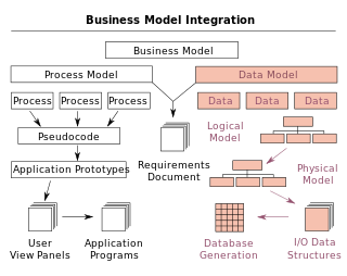
A logical data model or logical schema is a data model of a specific problem domain expressed independently of a particular database management product or storage technology but in terms of data structures such as relational tables and columns, object-oriented classes, or XML tags. This is as opposed to a conceptual data model, which describes the semantics of an organization without reference to technology.

<span class="mw-page-title-main">Physical schema</span> Representation of a data design

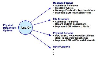
A physical data model is a representation of a data design as implemented, or intended to be implemented, in a database management system. In the lifecycle of a project it typically derives from a logical data model, though it may be reverse-engineered from a given database implementation. A complete physical data model will include all the database artifacts required to create relationships between tables or to achieve performance goals, such as indexes, constraint definitions, linking tables, partitioned tables or clusters. Analysts can usually use a physical data model to calculate storage estimates; it may include specific storage allocation details for a given database system.

<span class="mw-page-title-main">Snowflake schema</span> A logical arrangement of computing tables in a multidimensional database

In computing, a snowflake schema or snowflake model is a logical arrangement of tables in a multidimensional database such that the entity relationship diagram resembles a snowflake shape. The snowflake schema is represented by centralized fact tables which are connected to multiple dimensions. "Snowflaking" is a method of normalizing the dimension tables in a star schema. When it is completely normalized along all the dimension tables, the resultant structure resembles a snowflake with the fact table in the middle. The principle behind snowflaking is normalization of the dimension tables by removing low cardinality attributes and forming separate tables.

Object–relational impedance mismatch is a set of difficulties going between data in relational data stores and data in domain-driven object models. Relational Database Management Systems (RDBMS) is the standard method for storing data in a dedicated database, while object-orientated (OO) programming is the default method for business-centric design in programming languages. The problem lies in neither relational databases nor OO programming, but in the conceptual difficulty mapping between the two logic models. Both logical models are differently implementable using database servers, programming languages, design patterns, or other technologies. Issues range from application to enterprise scale, whenever stored relational data is used in domain-driven object models, and vice versa. Object-oriented data stores can trade this problem for other implementation difficulties.

<span class="mw-page-title-main">IDEF1X</span>

Integration DEFinition for information modeling (IDEF1X) is a data modeling language for the development of semantic data models. IDEF1X is used to produce a graphical information model which represents the structure and semantics of information within an environment or system.

An entity–attribute–value model (EAV) is a data model optimized for the space-efficient storage of sparse—or ad-hoc—property or data values, intended for situations where runtime usage patterns are arbitrary, subject to user variation, or otherwise unforeseeable using a fixed design. The use-case targets applications which offer a large or rich system of defined property types, which are in turn appropriate to a wide set of entities, but where typically only a small, specific selection of these are instantiated for a given entity. Therefore, this type of data model relates to the mathematical notion of a sparse matrix. EAV is also known as object–attribute–value model, vertical database model, and open schema.

Dimensional modeling (DM) is part of the Business Dimensional Lifecycle methodology developed by Ralph Kimball which includes a set of methods, techniques and concepts for use in data warehouse design. The approach focuses on identifying the key business processes within a business and modelling and implementing these first before adding additional business processes, as a bottom-up approach. An alternative approach from Inmon advocates a top down design of the model of all the enterprise data using tools such as entity-relationship modeling (ER).

<span class="mw-page-title-main">Database model</span> Type of data model

A database model is a type of data model that determines the logical structure of a database. It fundamentally determines in which manner data can be stored, organized and manipulated. The most popular example of a database model is the relational model, which uses a table-based format.

Entity Framework (EF) is an open source object–relational mapping (ORM) framework for ADO.NET. It was originally shipped as an integral part of .NET Framework, however starting with Entity Framework version 6.0 it has been delivered separately from the .NET Framework.

A document-oriented database, or document store, is a computer program and data storage system designed for storing, retrieving and managing document-oriented information, also known as semi-structured data.

A graph database (GDB) is a database that uses graph structures for semantic queries with nodes, edges, and properties to represent and store data. A key concept of the system is the graph. The graph relates the data items in the store to a collection of nodes and edges, the edges representing the relationships between the nodes. The relationships allow data in the store to be linked together directly and, in many cases, retrieved with one operation. Graph databases hold the relationships between data as a priority. Querying relationships is fast because they are perpetually stored in the database. Relationships can be intuitively visualized using graph databases, making them useful for heavily inter-connected data.

<span class="mw-page-title-main">Anchor modeling</span> Agile database modeling technique

Anchor modeling is an agile database modeling technique suited for information that changes over time both in structure and content. It provides a graphical notation used for conceptual modeling similar to that of entity-relationship modeling, with extensions for working with temporal data. The modeling technique involves four modeling constructs: the anchor, attribute, tie and knot, each capturing different aspects of the domain being modeled. The resulting models can be translated to physical database designs using formalized rules. When such a translation is done the tables in the relational database will mostly be in the sixth normal form.

The following is provided as an overview of and topical guide to databases:

References

  1. Teorey, T.J., Lightstone, S.S., et al., (2009). Database Design: Know it all.1st ed. Burlington, MA.: Morgan Kaufmann Publishers
  2. Teorey, T.; Lightstone, S. and Nadeau, T.(2005) Database Modeling & Design: Logical Design, 4th edition, Morgan Kaufmann Press. ISBN   0-12-685352-5
  3. Javed, Muhammad; Lin, Yuqing (2018). "Iterative Process for Generating ER Diagram from Unrestricted Requirements". Proceedings of the 13th International Conference on Evaluation of Novel Approaches to Software Engineering. SCITEPRESS – Science and Technology Publications: 192–204. doi: 10.5220/0006778701920204 . ISBN   978-989-758-300-1.
  4. Database design basics. (n.d.). Database design basics. Retrieved May 1, 2010, from https://support.office.com/en-US/article/Database-design-basics-EB2159CF-1E30-401A-8084-BD4F9C9CA1F5

Further reading