Related Research Articles

Computer-aided design (CAD) is the use of computers to aid in the creation, modification, analysis, or optimization of a design. This software is used to increase the productivity of the designer, improve the quality of design, improve communications through documentation, and to create a database for manufacturing. Designs made through CAD software help protect products and inventions when used in patent applications. CAD output is often in the form of electronic files for print, machining, or other manufacturing operations. The terms computer-aided drafting (CAD) and computer-aided design and drafting (CADD) are also used.
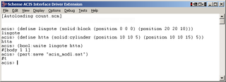
The 3D ACIS Modeler (ACIS) is a geometric modeling kernel developed by Spatial Corporation, part of Dassault Systèmes. ACIS is used by software developers in industries such as computer-aided design, computer-aided manufacturing, computer-aided engineering, architecture, engineering and construction, coordinate-measuring machine, 3D animation, and shipbuilding. ACIS provides software developers and manufacturers the underlying 3D modeling functionality.

Computer-aided manufacturing (CAM) also known as computer-aided modeling or computer-aided machining is the use of software to control machine tools in the manufacturing of work pieces. This is not the only definition for CAM, but it is the most common. It may also refer to the use of a computer to assist in all operations of a manufacturing plant, including planning, management, transportation and storage. Its primary purpose is to create a faster production process and components and tooling with more precise dimensions and material consistency, which in some cases, uses only the required amount of raw material, while simultaneously reducing energy consumption. CAM is now a system used in schools and lower educational purposes. CAM is a subsequent computer-aided process after computer-aided design (CAD) and sometimes computer-aided engineering (CAE), as the model generated in CAD and verified in CAE can be input into CAM software, which then controls the machine tool. CAM is used in many schools alongside CAD to create objects.
Solid modeling is a consistent set of principles for mathematical and computer modeling of three-dimensional shapes (solids). Solid modeling is distinguished within the broader related areas of geometric modeling and computer graphics, such as 3D modeling, by its emphasis on physical fidelity. Together, the principles of geometric and solid modeling form the foundation of 3D-computer-aided design, and in general, support the creation, exchange, visualization, animation, interrogation, and annotation of digital models of physical objects.

Computer-aided software engineering (CASE) is a domain of software tools used to design and implement applications. CASE tools are similar to and are partly inspired by computer-aided design (CAD) tools used for designing hardware products. CASE tools are intended to help develop high-quality, defect-free, and maintainable software. CASE software was often associated with methods for the development of information systems together with automated tools that could be used in the software development process.

SolidWorks is a brand within Dassault Systèmes that develops and markets software for solid modeling computer-aided design (CAD), computer-aided engineering (CAE), 3D CAD design, collaboration, analysis, and product data management. The company introduced one of the first 3D CAD applications designed to run on a desktop PC.
Computer Aided Industrial Design (CAID) is a subset of computer-aided design (CAD) software that can assist in creating the look-and-feel or industrial design aspects of a product in development.

In solid modeling and computer-aided design, boundary representation is a method for representing a 3D shape by defining the limits of its volume. A solid is represented as a collection of connected surface elements, which define the boundary between interior and exterior points.
CAD data exchange is a method of drawing data exchange used to translate between different computer-aided design (CAD) authoring systems or between CAD and other downstream CAx systems.

Open Cascade Technology (OCCT), formerly named CAS.CADE, is a development platform for 3D computer-aided design (CAD), computer-aided manufacturing (CAM), computer-aided engineering (CAE), etc. It is developed and supported by Open Cascade SAS company. It is free and open-source software released under the GNU Lesser General Public License (LGPL), version 2.1 only, which permits open source and proprietary uses.

Solid Edge is a 3D computer-aided design (CAD), parametric feature and synchronous technology solid modeling software. It runs on Microsoft Windows and provides solid modeling, assembly modelling and 2D orthographic view functions for mechanical designers. Through third party applications it has links to many other product lifecycle management (PLM) technologies.
Vellum Investment Partners, LLC, dba Ashlar-Vellum, is an American software company that develops Computer-aided design (CAD) and 3D modeling software for both the Macintosh and Microsoft Windows platforms. Ashlar-Vellum's interface, designed in 1988 by Dr. Martin Newell and Dan Fitzpatrick, featured an automated Drafting Assistant that found useful points in the geometry and allowed the artist to quickly connect to locations like the "midpoint" or "tangent".

BricsCAD® is a software application for computer-aided design (CAD), developed by Bricsys nv. The company was founded in 2002 by Erik de Keyser, a longtime CAD entrepreneur. In 2011 Bricsys acquired the intellectual property rights from Ledas for constraints-based parametric design tools, permitting the development of applications in the areas of direct modeling and assembly design. Bricsys is headquartered in Ghent, Belgium, and has additional development centers in Nizhny Novgorod and Novosibirsk, Russia; Bucharest, Romania and Singapore. Bricsys is a founding member of the Open Design Alliance, and joined the BuildingSMART International consortium in December 2016.
HOOPS Visualize is a 3D computer graphics software designed to render graphics across both mobile and desktop platforms. HOOPS Visualize provides 3D Graphics API to render CAD models. It's part of the HOOPS 3D Application Framework SDK. Since June 2018 it's licensed via Siemens PLM Software.

OpenSCAD is a free software application for creating solid 3D computer-aided design (CAD) objects. It is a script-only based modeller that uses its own description language; the 3D preview can be manipulated interactively, but cannot be interactively modified in 3D. Instead, an OpenSCAD script specifies geometric primitives and defines how they are modified and combined to render a 3D model. As such, the program performs constructive solid geometry (CSG). OpenSCAD is available for Windows, Linux, and macOS.

Digital Geometric Kernel is a software development framework and a set of components for enabling 3D computer graphics computer-aided design (3D/CAD) function in Windows applications, developed by DInsight.
Shape Data Limited is a computer software company in Cambridge, England that specialises in developing programs for engineering and manufacturing professionals.
Computer-aided design is the use of computers to aid in the creation, modification, analysis, or optimization of a design. Designers have used computers for calculations since their invention. CAD software was popularized and innovated in the 1960s, although various developments were made between the mid-1940s and 1950s. Digital computers were used in power system analysis or optimization as early as proto-"Whirlwind" in 1949. Circuit design theory or power network methodology was algebraic, symbolic, and often vector-based.
References
- ↑ "Ian Braid, Alan Grayer and Charles Lang, the 2008 Pierre Bézier Award Recipients". Sold Modeling Association. Retrieved 2 April 2016.
- ↑ Rogers, David; Earnshaw, Rae (2001-10-31). Computer Graphics Techniques:Theory and Practice. Springer. p. 399. ISBN 0-387-97237-4.
| | This article related to a type of software is a stub. You can help Wikipedia by expanding it. |