Related Research Articles
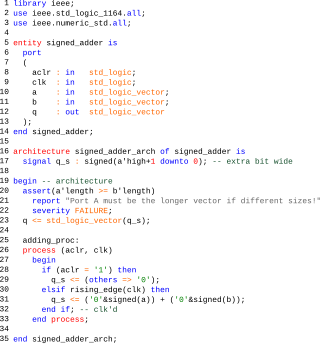
VHDL is a hardware description language that can model the behavior and structure of digital systems at multiple levels of abstraction, ranging from the system level down to that of logic gates, for design entry, documentation, and verification purposes. The language was developed for the US military VHSIC program in the 1980s, and has been standardized by the Institute of Electrical and Electronics Engineers (IEEE) as IEEE Std 1076; the latest version of which is IEEE Std 1076-2019. To model analog and mixed-signal systems, an IEEE-standardized HDL based on VHDL called VHDL-AMS has been developed.
In computer engineering, a hardware description language (HDL) is a specialized computer language used to describe the structure and behavior of electronic circuits, most commonly to design ASICs and program FPGAs.
Electronic design automation (EDA), also referred to as electronic computer-aided design (ECAD), is a category of software tools for designing electronic systems such as integrated circuits and printed circuit boards. The tools work together in a design flow that chip designers use to design and analyze entire semiconductor chips. Since a modern semiconductor chip can have billions of components, EDA tools are essential for their design; this article in particular describes EDA specifically with respect to integrated circuits (ICs).

In computer science, model checking or property checking is a method for checking whether a finite-state model of a system meets a given specification. This is typically associated with hardware or software systems, where the specification contains liveness requirements as well as safety requirements.
In digital circuit design, register-transfer level (RTL) is a design abstraction which models a synchronous digital circuit in terms of the flow of digital signals (data) between hardware registers, and the logical operations performed on those signals.
In computer engineering, logic synthesis is a process by which an abstract specification of desired circuit behavior, typically at register transfer level (RTL), is turned into a design implementation in terms of logic gates, typically by a computer program called a synthesis tool. Common examples of this process include synthesis of designs specified in hardware description languages, including VHDL and Verilog. Some synthesis tools generate bitstreams for programmable logic devices such as PALs or FPGAs, while others target the creation of ASICs. Logic synthesis is one step in circuit design in the electronic design automation, the others are place and route and verification and validation.
In electronic design, a semiconductor intellectual property core, IP core or IP block is a reusable unit of logic, cell, or integrated circuit layout design that is the intellectual property of one party. IP cores can be licensed to another party or owned and used by a single party. The term comes from the licensing of the patent or source code copyright that exists in the design. Designers of system on chip (SoC), application-specific integrated circuits (ASIC) and systems of field-programmable gate array (FPGA) logic can use IP cores as building blocks.

In semiconductor design, standard-cell methodology is a method of designing application-specific integrated circuits (ASICs) with mostly digital-logic features. Standard-cell methodology is an example of design abstraction, whereby a low-level very-large-scale integration (VLSI) layout is encapsulated into an abstract logic representation.
SystemVerilog, standardized as IEEE 1800, is a hardware description and hardware verification language used to model, design, simulate, test and implement electronic systems. SystemVerilog is based on Verilog and some extensions, and since 2008, Verilog is now part of the same IEEE standard. It is commonly used in the semiconductor and electronic design industry as an evolution of Verilog.

Integrated circuit design, semiconductor design, chip design or IC design, is a sub-field of electronics engineering, encompassing the particular logic and circuit design techniques required to design integrated circuits, or ICs. ICs consist of miniaturized electronic components built into an electrical network on a monolithic semiconductor substrate by photolithography.
An EDA database is a database specialized for the purpose of electronic design automation. These application specific databases are required because general purpose databases have historically not provided enough performance for EDA applications.
Functional verification is the task of verifying that the logic design conforms to specification. Functional verification attempts to answer the question "Does this proposed design do what is intended?" This is complex and takes the majority of time and effort in most large electronic system design projects. Functional verification is a part of more encompassing design verification, which, besides functional verification, considers non-functional aspects like timing, layout and power.
Design Closure is a part of the digital electronic design automation workflow by which an integrated circuit design is modified from its initial description to meet a growing list of design constraints and objectives.

The Layout Versus Schematic (LVS) is the class of electronic design automation (EDA) verification software that determines whether a particular integrated circuit layout corresponds to the original schematic or circuit diagram of the design.

An and-inverter graph (AIG) is a directed, acyclic graph that represents a structural implementation of the logical functionality of a circuit or network. An AIG consists of two-input nodes representing logical conjunction, terminal nodes labeled with variable names, and edges optionally containing markers indicating logical negation. This representation of a logic function is rarely structurally efficient for large circuits, but is an efficient representation for manipulation of boolean functions. Typically, the abstract graph is represented as a data structure in software.
An engineering change order (ECO), also called an engineering change notice (ECN), engineering change (EC), or engineering release notice(ERN), is an artifact used to implement changes to components or end products. The ECO is utilized to control and coordinate changes to product designs that evolve over time.
Logic optimization is a process of finding an equivalent representation of the specified logic circuit under one or more specified constraints. This process is a part of a logic synthesis applied in digital electronics and integrated circuit design.

In integrated circuit design, physical design is a step in the standard design cycle which follows after the circuit design. At this step, circuit representations of the components of the design are converted into geometric representations of shapes which, when manufactured in the corresponding layers of materials, will ensure the required functioning of the components. This geometric representation is called integrated circuit layout. This step is usually split into several sub-steps, which include both design and verification and validation of the layout.
High-level synthesis (HLS), sometimes referred to as C synthesis, electronic system-level (ESL) synthesis, algorithmic synthesis, or behavioral synthesis, is an automated design process that takes an abstract behavioral specification of a digital system and finds a register-transfer level structure that realizes the given behavior.
High-level verification (HLV), or electronic system-level (ESL) verification, is the task to verify ESL designs at high abstraction level, i.e., it is the task to verify a model that represents hardware above register-transfer level (RTL) abstract level. For high-level synthesis, HLV is to HLS as functional verification is to logic synthesis.
References
- Electronic Design Automation For Integrated Circuits Handbook, by Lavagno, Martin, and Scheffer, ISBN 0-8493-3096-3 A survey of the field. This article was derived, with permission, from Volume 2, Chapter 4, Equivalence Checking, by Fabio Somenzi and Andreas Kuehlmann.
- R.E. Bryant, Graph-based algorithms for Boolean function manipulation , IEEE Transactions on Computers., C-35, pp. 677–691, 1986. The original reference on BDDs.
- Sequential equivalence checking for RTL models. Nikhil Sharma, Gagan Hasteer and Venkat Krishnaswamy. EE Times.