Related Research Articles
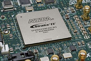
A field-programmable gate array (FPGA) is an integrated circuit designed to be configured after manufacturing. The FPGA configuration is generally specified using a hardware description language (HDL), similar to that used for an application-specific integrated circuit (ASIC). Circuit diagrams were previously used to specify the configuration, but this is increasingly rare due to the advent of electronic design automation tools.
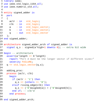
The VHSIC Hardware Description Language (VHDL) is a hardware description language (HDL) that can model the behavior and structure of digital systems at multiple levels of abstraction, ranging from the system level down to that of logic gates, for design entry, documentation, and verification purposes. Since 1987, VHDL has been standardized by the Institute of Electrical and Electronics Engineers (IEEE) as IEEE Std 1076; the latest version of which is IEEE Std 1076-2019. To model analog and mixed-signal systems, an IEEE-standardized HDL based on VHDL called VHDL-AMS has been developed.
Verilog, standardized as IEEE 1364, is a hardware description language (HDL) used to model electronic systems. It is most commonly used in the design and verification of digital circuits at the register-transfer level of abstraction. It is also used in the verification of analog circuits and mixed-signal circuits, as well as in the design of genetic circuits. In 2009, the Verilog standard was merged into the SystemVerilog standard, creating IEEE Standard 1800-2009. Since then, Verilog is officially part of the SystemVerilog language. The current version is IEEE standard 1800-2017.
In computer engineering, a hardware description language (HDL) is a specialized computer language used to describe the structure and behavior of electronic circuits, and most commonly, digital logic circuits.
Electronic design automation (EDA), also referred to as electronic computer-aided design (ECAD), is a category of software tools for designing electronic systems such as integrated circuits and printed circuit boards. The tools work together in a design flow that chip designers use to design and analyze entire semiconductor chips. Since a modern semiconductor chip can have billions of components, EDA tools are essential for their design; this article in particular describes EDA specifically with respect to integrated circuits (ICs).
In digital circuit design, register-transfer level (RTL) is a design abstraction which models a synchronous digital circuit in terms of the flow of digital signals (data) between hardware registers, and the logical operations performed on those signals.
SystemC is a set of C++ classes and macros which provide an event-driven simulation interface. These facilities enable a designer to simulate concurrent processes, each described using plain C++ syntax. SystemC processes can communicate in a simulated real-time environment, using signals of all the datatypes offered by C++, some additional ones offered by the SystemC library, as well as user defined. In certain respects, SystemC deliberately mimics the hardware description languages VHDL and Verilog, but is more aptly described as a system-level modeling language.
Formal equivalence checking process is a part of electronic design automation (EDA), commonly used during the development of digital integrated circuits, to formally prove that two representations of a circuit design exhibit exactly the same behavior.
SystemVerilog, standardized as IEEE 1800, is a hardware description and hardware verification language used to model, design, simulate, test and implement electronic systems. SystemVerilog is based on Verilog and some extensions, and since 2008, Verilog is now part of the same IEEE standard. It is commonly used in the semiconductor and electronic design industry as an evolution of Verilog.
Static timing analysis (STA) is a simulation method of computing the expected timing of a synchronous digital circuit without requiring a simulation of the full circuit.

Integrated circuit design, or IC design, is a sub-field of electronics engineering, encompassing the particular logic and circuit design techniques required to design integrated circuits, or ICs. ICs consist of miniaturized electronic components built into an electrical network on a monolithic semiconductor substrate by photolithography.
Functional verification is the task of verifying that the logic design conforms to specification. Functional verification attempts to answer the question "Does this proposed design do what is intended?" This is complex and takes the majority of time and effort in most large electronic system design projects. Functional verification is a part of more encompassing design verification, which, besides functional verification, considers non-functional aspects like timing, layout and power.
In integrated circuit design, hardware emulation is the process of imitating the behavior of one or more pieces of hardware with another piece of hardware, typically a special purpose emulation system. The emulation model is usually based on a hardware description language source code, which is compiled into the format used by emulation system. The goal is normally debugging and functional verification of the system being designed. Often an emulator is fast enough to be plugged into a working target system in place of a yet-to-be-built chip, so the whole system can be debugged with live data. This is a specific case of in-circuit emulation.
Verilog-AMS is a derivative of the Verilog hardware description language that includes Analog and Mixed-Signal extensions (AMS) in order to define the behavior of analog and mixed-signal systems. It extends the event-based simulator loops of Verilog/SystemVerilog/VHDL, by a continuous-time simulator, which solves the differential equations in analog-domain. Both domains are coupled: analog events can trigger digital actions and vice versa.

Electronic circuit simulation uses mathematical models to replicate the behavior of an actual electronic device or circuit. Simulation software allows for modeling of circuit operation and is an invaluable analysis tool. Due to its highly accurate modeling capability, many colleges and universities use this type of software for the teaching of electronics technician and electronics engineering programs. Electronics simulation software engages its users by integrating them into the learning experience. These kinds of interactions actively engage learners to analyze, synthesize, organize, and evaluate content and result in learners constructing their own knowledge.
Simulation software is based on the process of modeling a real phenomenon with a set of mathematical formulas. It is, essentially, a program that allows the user to observe an operation through simulation without actually performing that operation. Simulation software is used widely to design equipment so that the final product will be as close to design specs as possible without expensive in process modification. Simulation software with real-time response is often used in gaming, but it also has important industrial applications. When the penalty for improper operation is costly, such as airplane pilots, nuclear power plant operators, or chemical plant operators, a mock up of the actual control panel is connected to a real-time simulation of the physical response, giving valuable training experience without fear of a disastrous outcome.
Aldec, Inc. is a privately owned electronic design automation company based in Henderson, Nevada that provides software and hardware used in creation and verification of digital designs targeting FPGA and ASIC technologies.
High-level synthesis (HLS), sometimes referred to as C synthesis, electronic system-level (ESL) synthesis, algorithmic synthesis, or behavioral synthesis, is an automated design process that takes an abstract behavioral specification of a digital system and finds a register-transfer level structure that realizes the given behavior.
Verilator is a free and open-source software tool which converts Verilog to a cycle-accurate behavioral model in C++ or SystemC. The generated models are cycle-accurate and 2-state; as a consequence, the models typically offer higher performance than the more widely used event-driven simulators, which can model behavior within the clock cycle. Verilator is now used within academic research, open source projects and for commercial semiconductor development. It is part of the growing body of free EDA software.
Catapult C Synthesis, a commercial electronic design automation product of Mentor Graphics, is a high-level synthesis tool, sometimes called algorithmic synthesis or ESL synthesis. Catapult C takes ANSI C/C++ and SystemC inputs and generates register transfer level (RTL) code targeted to FPGAs and ASICs.
References
- ↑ Laung-Terng Wang; Yao-Wen Chang; Kwang-Ting (Tim) Cheng (11 March 2009). Electronic Design Automation: Synthesis, Verification, and Test. Morgan Kaufmann. ISBN 978-0-08-092200-3.
- ↑ V. Litovski; Mark Zwolinski (31 December 1996). VLSI Circuit Simulation and Optimization. Springer Science & Business Media. ISBN 978-0-412-63860-2.
- ↑ Bombieri, Nicola; Fummi, Franco; Pravadelli, Graziano (May 2006). Hardware Design and Simulation for Verification. Lecture Notes in Computer Science. pp. 1–29.
- ↑ Software system for distributed event-driven logic simulation. Ladyzhensky Y.V., Popoff Y.V. Proceedings of IEEE East-West Design & Test Workshop(EWDTW'05). IEEE EWDTW, 2005, p.119-122 ISBN 966-659-113-8
- ↑ Wang, Tsu-Hua and Tan, Chong Guan (1995). Practical code coverage for Verilog. 1995 IEEE International Verilog HDL Conference. IEEE. pp. 99–104.
{{cite conference}}: CS1 maint: multiple names: authors list (link) - ↑ Jou, Jing-Yang and Liu, Chien-Nan Jimmy (1999). Coverage analysis techniques for HDL design validation. Asia Pacific CHip Design Languages. pp. 48–55.
{{cite conference}}: CS1 maint: multiple names: authors list (link) - ↑ "Network Modeling and Simulation Environment" (PDF). Defense Technical Information Center. Retrieved January 1, 2023.
- ↑ Electronic Design Automation For Integrated Circuits Handbook, by Lavagno, Martin, and Scheffer, ISBN 0-8493-3096-3, a survey of the field of EDA. The above summary was derived, with permission, from Volume I, Chapter 16, Digital Simulation, by John Sanguinetti.