Commercial FM broadcasting transmitter at radio station WDET-FM, Wayne State University, Detroit, US. It broadcasts at 101.9 MHz with a radiated power of 48 kW.
The term is popularly used more specifically to refer to a broadcast transmitter, a transmitter used in broadcasting, as in FM radio transmitter or television transmitter. This usage typically includes both the transmitter proper, the antenna, and often the building it is housed in.
A transmitter can be a separate piece of electronic equipment, or an electrical circuit within another electronic device. A transmitter and a receiver combined in one unit is called a transceiver. The purpose of most transmitters is radio communication of information over a distance. The information is provided to the transmitter in the form of an electronic signal called the modulation signal, such as an audio (sound) signal from a microphone, a video (TV) signal from a video camera, or in wireless networking devices, a digital signal from a computer. The transmitter generates a radio frequency signal which when applied to the antenna produces the radio waves, called the carrier signal. It combines the carrier with the modulation signal, a process called modulation. The information can be added to the carrier in several different ways, in different types of transmitters. In an amplitude modulation (AM) transmitter, the information is added to the radio signal by varying its amplitude. In a frequency modulation (FM) transmitter, it is added by varying the radio signal's frequency slightly. Many other types of modulation are also used.
The radio signal from the transmitter is applied to the antenna, which radiates the energy as radio waves. The antenna may be enclosed inside the case or attached to the outside of the transmitter, as in portable devices such as cell phones, walkie-talkies, and garage door openers. In more powerful transmitters, the antenna may be located on top of a building or on a separate tower, and connected to the transmitter by a feed line, that is a transmission line.
Radio transmitters
Elcom Bauer model 701B 1100 watt AM broadcast transmitter
35kW, Continental 816R-5B FM transmitter, belonging to American FM radio station KWNR broadcasting on 95.5MHz in Las Vegas
Modern amateur radiotransceiver, the ICOM IC-746PRO. It can transmit on the amateur bands from 1.8MHz to 144MHz with an output power of 100W
A CB radio transceiver in a truck, a two way radio transmitting on 27MHz with a power of 4W, that can be operated without a license
A cellphone has several transmitters: a duplex cell transceiver, a Wi-Fi modem, and a Bluetooth modem.
Both the handset and the base of a cordless phone contain low power 2.4GHz radio transmitters to communicate with each other.
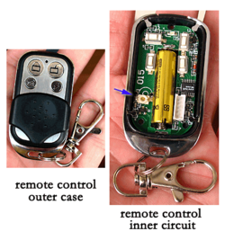
A garage door opener control contains a low-power 2.4GHz transmitter that sends coded commands to the garage door mechanism to open or close.
A laptop computer and home wireless router (background) which connects it to the Internet, creating a home Wi-Fi network. Both have Wi-Fi modems, automated microwave transmitters and receivers operating on 2.4GHz which exchange data packets with the internet service provider (ISP).
A Bluetooth earbud with microphone. It has a Bluetooth modem to exchange audio with a cell phone
Animation of a half-wave dipole antenna transmitting radio waves, showing the electric field lines. The antenna in the center is two vertical metal rods, with an alternating current applied at its center from a radio transmitter (not shown). The voltage charges the two sides of the antenna alternately positive (+) and negative (−). Loops of electric field (black lines) leave the antenna and travel away at the speed of light; these are the radio waves. This animation shows the action slowed enormously
Electromagnetic waves are radiated by electric charges when they are accelerated.[1][2]Radio waves, electromagnetic waves of radio frequency, are generated by time-varying electric currents, consisting of electrons flowing through a metal conductor called an antenna which are changing their velocity and thus accelerating.[3][2] An alternating current flowing back and forth in an antenna will create an oscillating magnetic field around the conductor. The alternating voltage will also charge the ends of the conductor alternately positive and negative, creating an oscillating electric field around the conductor. If the frequency of the oscillations is high enough, in the radio frequency range above about 20kHz, the oscillating coupled electric and magnetic fields will radiate away from the antenna into space as an electromagnetic wave, a radio wave.
A radio transmitter is an electronic circuit which transforms electric power from a power source, a battery or mains power, into a radio frequency alternating current to apply to the antenna, and the antenna radiates the energy from this current as radio waves.[4] The transmitter also encodes information such as an audio or video signal into the radio frequency current to be carried by the radio waves. When they strike the antenna of a radio receiver, the waves excite similar (but less powerful) radio frequency currents in it. The radio receiver extracts the information from the received waves.
Components
A practical radio transmitter mainly consists of the following parts:
In high power transmitters, a power supply circuit to transform the input electrical power to the higher voltages needed to produce the required power output.
An electronic oscillator circuit to generate the radio frequency signal. This usually generates a sine wave of constant amplitude, called the carrier wave because it produces the radio waves which "carry" the information through space. In most modern transmitters, this is a crystal oscillator in which the frequency is precisely controlled by the vibrations of a quartz crystal. The frequency of the carrier wave is considered the frequency of the transmitter.
A modulator circuit to add the information to be transmitted to the carrier wave produced by the oscillator. This is done by varying some aspect of the carrier wave. The information is provided to the transmitter as an electronic signal called the modulation signal. The modulation signal may be an audio signal, which represents sound, a video signal which represents moving images, or for data in the form of a binarydigital signal which represents a sequence of bits, a bitstream. Different types of transmitters use different modulation methods to transmit information:
In an AM (amplitude modulation) transmitter the amplitude (strength) of the carrier wave is varied in proportion to the modulation signal.
In an FSK (frequency-shift keying) transmitter, which transmits digital data, the frequency of the carrier is shifted between two frequencies which represent the two binary digits, 0 and 1.
OFDM (orthogonal frequency-division multiplexing) is a family of complicated digital modulation methods very widely used in high bandwidth systems such as Wi-Fi networks, cellphones, digital television broadcasting, and digital audio broadcasting (DAB) to transmit digital data using a minimum of radio spectrum bandwidth. OFDM has higher spectral efficiency and more resistance to fading than AM or FM. In OFDM multiple radio carrier waves closely spaced in frequency are transmitted within the radio channel, with each carrier modulated with bits from the incoming bitstream so multiple bits are being sent simultaneously, in parallel. At the receiver the carriers are demodulated and the bits are combined in the proper order into one bitstream.
Many other types of modulation are also used. In large transmitters the oscillator and modulator together are often referred to as the exciter.[5]
A radio frequency (RF) amplifier to increase the power of the signal, to increase the range of the radio waves.
An impedance matching (antenna tuner) circuit to transform the output impedance of the transmitter to match the impedance of the antenna (or the transmission line to the antenna), to transfer power efficiently to the antenna. If these impedances are not equal, it causes a condition called standing waves, in which the power is reflected back from the antenna toward the transmitter, wasting power and sometimes overheating the transmitter.
In higher frequency transmitters, in the UHF and microwave range, free running oscillators are unstable at the output frequency. Older designs used an oscillator at a lower frequency, which was multiplied by frequency multipliers to get a signal at the desired frequency. Modern designs more commonly use an oscillator at the operating frequency which is stabilized by phase locking to a very stable lower frequency reference, usually a crystal oscillator.
Regulation
Two radio transmitters in the same area that attempt to transmit on the same frequency will interfere with each other, causing garbled reception, so neither transmission may be received clearly. Interference with radio transmissions can not only have a large economic cost, it can be life-threatening (for example, in the case of interference with emergency communications or air traffic control).
For this reason, in most countries, use of transmitters is strictly controlled by law. Transmitters must be licensed by governments, under a variety of license classes depending on use such as broadcast, marine radio, Airband, Amateur and are restricted to certain frequencies and power levels. A body called the International Telecommunication Union (ITU) allocates the frequency bands in the radio spectrum to various classes of users. In some classes, each transmitter is given a unique call sign consisting of a string of letters and numbers which must be used as an identifier in transmissions. The operator of the transmitter usually must hold a government license, such as a general radiotelephone operator license, which is obtained by passing a test demonstrating adequate technical and legal knowledge of safe radio operation.
Hertz discovering radio waves in 1887 with his first primitive radio transmitter (background).
The first primitive radio transmitters (called spark gap transmitters) were built by German physicist Heinrich Hertz in 1887 during his pioneering investigations of radio waves. These generated radio waves by a high voltage spark between two conductors. Beginning in 1895, Guglielmo Marconi developed the first practical radio communication systems using these transmitters, and radio began to be used commercially around 1900. Spark transmitters could not transmit audio (sound) and instead transmitted information by radiotelegraphy: the operator tapped on a telegraph key which turned the transmitter on-and-off to produce radio wave pulses spelling out text messages in telegraphic code, usually Morse code. At the receiver, these pulses were sometimes directly recorded on paper tapes, but more common was audible reception. The pulses were audible as beeps in the receiver's earphones, which were translated back to text by an operator who knew Morse code. These spark-gap transmitters were used during the first three decades of radio (1887–1917), called the wireless telegraphy or "spark" era. Because they generated damped waves, spark transmitters were electrically "noisy". Their energy was spread over a broad band of frequencies, creating radio noise which interfered with other transmitters. Damped wave emissions were banned by international law in 1934.
Two short-lived competing transmitter technologies came into use after the turn of the century, which were the first continuous wave transmitters: the arc converter (Poulsen arc) in 1904 and the Alexanderson alternator around 1910, which were used into the 1920s.
Spark oscillator similar to Hertz's, 1902. Visible are antenna consisting of 2 wires ending in metal plates (E), spark gap (D), induction coil (A), auto battery (B), and telegraph key(C).
High power spark gap radiotelegraphy transmitter in Australia around 1910.
1 MW US Navy Poulsen arc transmitter which generated continuous waves using an electric arc in a magnetic field, a technology used for a brief period from 1903 until vacuum tubes took over in the 20s
An Alexanderson alternator, a huge rotating machine used as a radio transmitter at very low frequency from about 1910 until World War 2
One of the BBC's first broadcast transmitters, early 1920s, London. The 4 triode tubes, connected in parallel to form an oscillator, each produced around 4 kilowatts with 12 thousand volts on their anodes.
Armstrong's first experimental FM broadcast transmitter W2XDG, in the Empire State Building, New York City, used for secret tests 1934–1935. It transmitted on 41MHz at a power of 2kW.
Transmitter assembly of a 20kW, 9.375GHz air traffic controlradar, 1947. The magnetron tube mounted between two magnets (right) produces microwaves which pass from the aperture (left) into a waveguide which conducts them to the dish antenna.
↑Brain, Marshall (2000-12-07). "How Radio Works". HowStuffWorks.com. Retrieved 2009-09-11.
↑Welton, Jeff (2018). Cavell, Garrison (ed.). VHF (FM) Radio Transmitters in National Association of Broadcasters Engineering Handbook, 11th Edition. New York: Routledge. pp.1331–1334. ISBN9781138930513.
This page is based on this Wikipedia article Text is available under the CC BY-SA 4.0 license; additional terms may apply. Images, videos and audio are available under their respective licenses.