History
Fessenden, more than any other person, is responsible for developing amplitude modulation (AM) radio transmission around 1900. While working to develop AM transmitters, he realized that the radio wave detectors used in existing radio receivers were not suitable to receive AM signals. The radio transmitters of the time transmitted information by radiotelegraphy; the transmitter was turned on and off by the operator using a switch called a telegraph key producing pulses of radio waves, to transmit text data using Morse code. Thus, receivers didn't have to extract an audio signal from the radio signal, but only detected the presence or absence of the radio frequency to produce "clicks" in the earphone representing the pulses of Morse code. The device that did this was called a "detector". The detector used in receivers of that day, called a coherer, simply acted as a switch, that conducted current in the presence of radio waves, and thus did not have the capability to demodulate, or extract the audio signal from, an amplitude-modulated radio wave.
The simplest way to extract the sound waveform from an AM signal is to rectify it; remove the oscillations on one side of the wave, converting it from an alternating current to a varying direct current. The variations in the amplitude of the radio wave that represent the sound waveform will cause variations in the current, and thus can be converted to sound by an earphone. To do this a rectifier is required, an electrical component that conducts electric current in only one direction and blocks current in the opposite direction. It was known at the time that passing current through solutions of electrolytes such as acids could have this unilateral conduction property.
In 1902 Fessenden developed what he called a "barretter" detector that would rectify an AM signal, but it was not very sensitive. The barretter used a fine platinum wire, called Wollaston wire, manufactured as a platinum core in a silver sheath that had to be stripped off with acid. In the process of stripping some Wollaston wire, Fessenden left it immersed in acid too long, eating away most of the wire until only a tip remained in contact with the solution; he noted that it responded well to radio signals being generated nearby, and could be used as new type of detector.
This story was disputed at the time, with credit for the discovery also given to Michael I. Pupin, W. Schloemilch, Hugo Gernsback and others. However, it is apparent that Fessenden was the first to put the device to practical use.
Description
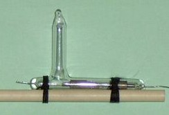
Picture of Fessenden's barretter and diagram showing parts. It included a reel of wire so that as the tip dissolved in the acid more wire could be lowered into the cup.
The action of this detector is based upon the fact that only the tip of a platinum wire a few hundred-thousandths of an inch in diameter is immersed in an electrolyte solution, and a small D.C. voltage bias is applied to the cell thus formed. [6] Platinum is used because other metals are too quickly dissolved in the acid. The applied bias current decomposes the solution by electrolysis into tiny gas bubbles that cling to the metal point insulating the metal tip from the solution thus reducing the bias current. An incoming R.F. current can flow better in the direction across the point that makes the point more negative. That recombines the gases and increases point exposure to the liquid. RF current flow in the direction that makes the point more positive only reinforces the resistance from the gaseous blocking of the point. Detection results from this asymmetrical flow.
In practical use, a series circuit is made of the detector, headphones, and a battery with a potentiometer. The wire is made positive, and the signal to be demodulated is applied directly to it; a small (about 5 ml) platinum cup filled with either sulfuric or nitric acid completes the headphone circuit, and is also connected to ground to complete the signal circuit. To adjust the cell, the point of the wire electrode is dipped into the electrolyte and the potentiometer adjusted until a hissing noise is heard in the headphones. The potentiometer setting is then moved to reduce the current until the noise just ceases, at which point the detector is in its most sensitive state.
It was found that strong atmospheric noise would render it insensitive, requiring that the device be rebiased after each strong burst of static interference.

Amplitude modulation (AM) is a modulation technique used in electronic communication, most commonly for transmitting messages with a radio wave. In amplitude modulation, the amplitude of the wave is varied in proportion to that of the message signal, such as an audio signal. This technique contrasts with angle modulation, in which either the frequency of the carrier wave is varied, as in frequency modulation, or its phase, as in phase modulation.

Wireless telegraphy or radiotelegraphy is the transmission of text messages by radio waves, analogous to electrical telegraphy using cables. Before about 1910, the term wireless telegraphy was also used for other experimental technologies for transmitting telegraph signals without wires. In radiotelegraphy, information is transmitted by pulses of radio waves of two different lengths called "dots" and "dashes", which spell out text messages, usually in Morse code. In a manual system, the sending operator taps on a switch called a telegraph key which turns the transmitter on and off, producing the pulses of radio waves. At the receiver the pulses are audible in the receiver's speaker as beeps, which are translated back to text by an operator who knows Morse code.

A heterodyne is a signal frequency that is created by combining or mixing two other frequencies using a signal processing technique called heterodyning, which was invented by Canadian inventor-engineer Reginald Fessenden. Heterodyning is used to shift signals from one frequency range into another, and is also involved in the processes of modulation and demodulation. The two input frequencies are combined in a nonlinear signal-processing device such as a vacuum tube, transistor, or diode, usually called a mixer.
Demodulation is the process of extracting the original information-bearing signal from a carrier wave. A demodulator is an electronic circuit that is used to recover the information content from the modulated carrier wave. There are many types of modulation, and there are many types of demodulators. The signal output from a demodulator may represent sound, images or binary data.
AM broadcasting is radio broadcasting using amplitude modulation (AM) transmissions. It was the first method developed for making audio radio transmissions, and is still used worldwide, primarily for medium wave transmissions, but also on the longwave and shortwave radio bands.

A crystal radio receiver, also called a crystal set, is a simple radio receiver, popular in the early days of radio. It uses only the power of the received radio signal to produce sound, needing no external power. It is named for its most important component, a crystal detector, originally made from a piece of crystalline mineral such as galena. This component is now called a diode.
The coherer was a primitive form of radio signal detector used in the first radio receivers during the wireless telegraphy era at the beginning of the 20th century. Its use in radio was based on the 1890 findings of French physicist Édouard Branly and adapted by other physicists and inventors over the next ten years. The device consists of a tube or capsule containing two electrodes spaced a small distance apart with loose metal filings in the space between. When a radio frequency signal is applied to the device, the metal particles would cling together or "cohere", reducing the initial high resistance of the device, thereby allowing a much greater direct current to flow through it. In a receiver, the current would activate a bell, or a Morse paper tape recorder to make a record of the received signal. The metal filings in the coherer remained conductive after the signal (pulse) ended so that the coherer had to be "decohered" by tapping it with a clapper actuated by an electromagnet, each time a signal was received, thereby restoring the coherer to its original state. Coherers remained in widespread use until about 1907, when they were replaced by more sensitive electrolytic and crystal detectors.

The Audion was an electronic detecting or amplifying vacuum tube invented by American electrical engineer Lee de Forest as a diode in 1906. Improved, it was patented as the first triode in 1908, consisting of an evacuated glass tube containing three electrodes: a heated filament, a grid, and a plate. It is important in the history of technology because it was the first widely used electronic device which could amplify. A low power signal at the grid could control much more power in the plate circuit.

An envelope detector is an electronic circuit that takes a (relatively) high-frequency signal as input and outputs the envelope of the original signal.

In radio communications, a radio receiver, also known as a receiver, a wireless, or simply a radio, is an electronic device that receives radio waves and converts the information carried by them to a usable form. It is used with an antenna. The antenna intercepts radio waves and converts them to tiny alternating currents which are applied to the receiver, and the receiver extracts the desired information. The receiver uses electronic filters to separate the desired radio frequency signal from all the other signals picked up by the antenna, an electronic amplifier to increase the power of the signal for further processing, and finally recovers the desired information through demodulation.

A spark-gap transmitter is an obsolete type of radio transmitter which generates radio waves by means of an electric spark. Spark-gap transmitters were the first type of radio transmitter, and were the main type used during the wireless telegraphy or "spark" era, the first three decades of radio, from 1887 to the end of World War I. German physicist Heinrich Hertz built the first experimental spark-gap transmitters in 1887, with which he proved the existence of radio waves and studied their properties.

A crystal detector is a type of electronic component used in some early 20th century radio receivers. It consists of a piece of crystalline mineral that rectifies an alternating current radio signal. It was employed as a detector (demodulator) to extract the audio modulation signal from the modulated carrier, to produce the sound in the earphones. It was the first type of semiconductor diode, and one of the first semiconductor electronic devices. The most common type was the so-called cat's whisker detector, which consisted of a piece of crystalline mineral, usually galena, with a fine wire touching its surface.
The magnetic detector or Marconi magnetic detector, sometimes called the "Maggie", was an early radio wave detector used in some of the first radio receivers to receive Morse code messages during the wireless telegraphy era around the turn of the 20th century. Developed in 1902 by radio pioneer Guglielmo Marconi from a method invented in 1895 by New Zealand physicist Ernest Rutherford, it was used in Marconi wireless stations until around 1912, when it was superseded by vacuum tubes. It was widely used on ships because of its reliability and insensitivity to vibration. A magnetic detector was part of the wireless apparatus in the radio room of the RMS Titanic which was used to summon help during its famous 15 April 1912 sinking.
The hot-wire barretter was a demodulating detector, invented in 1902 by Reginald Fessenden, that found limited use in early radio receivers. In effect, it was a highly sensitive thermoresistor, which could demodulate amplitude-modulated signals, something that the coherer could not do.

In radio, a detector is a device or circuit that extracts information from a modulated radio frequency current or voltage. The term dates from the first three decades of radio (1888–1918). Unlike modern radio stations which transmit sound on an uninterrupted carrier wave, early radio stations transmitted information by radiotelegraphy. The transmitter was switched on and off to produce long or short periods of radio waves, spelling out text messages in Morse code. Therefore, early radio receivers could reproduce the Morse code "dots" and "dashes" by simply distinguishing between the presence or absence of a radio signal. The device that performed this function in the receiver circuit was called a detector. A variety of different detector devices, such as the coherer, electrolytic detector, magnetic detector and the crystal detector, were used during the wireless telegraphy era until superseded by vacuum tube technology.

The autodyne circuit was an improvement to radio signal amplification using the De Forest Audion vacuum tube amplifier. By allowing the tube to oscillate at a frequency slightly different from the desired signal, the sensitivity over other receivers was greatly improved. The autodyne circuit was invented by Edwin Howard Armstrong of Columbia University, New York, NY. He inserted a tuned circuit in the output circuit of the Audion vacuum tube amplifier. By adjusting the tuning of this tuned circuit, Armstrong was able to dramatically increase the gain of the Audion amplifier. Further increase in tuning resulted in the Audion amplifier reaching self-oscillation.
A tikker, alternately spelled ticker, was a vibrating interrupter used in early wireless telegraphy radio receivers such as crystal radio receivers in order to receive continuous wave (CW) radiotelegraphy signals.

In electronics, a plate detector is a vacuum tube circuit in which an amplifying tube having a control grid is operated in a non-linear region of its grid voltage versus plate current transfer characteristic, usually near plate current cutoff, to demodulate amplitude modulated carrier signal. This differs from the grid leak detector, which utilizes the non-linearity of the grid voltage versus grid current characteristic for demodulation. It also differs from the diode detector, which is a two-terminal device.

The ratio detector is a type of detector circuit, commonly used in radio receivers for demodulating frequency modulated (FM) signal.

An audion receiver makes use of a single vacuum tube or transistor to detect and amplify signals. It is so called because it originally used the audion tube as the active element. Unlike a crystal detector or Fleming valve detector, the audion provided amplification of the signal as well as detection. The audion was invented by Lee De Forest.


