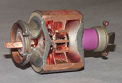
Magnetron with section removed to exhibit the cavities. The cathode in the center is not visible. The antenna emitting microwaves is at the left. The magnets producing a field parallel to the long axis of the device are not shown.A similar magnetron with a different section removed. Central cathode is visible; antenna conducting microwaves at the top; magnets are not shown.Obsolete 9 GHz magnetron tube and magnets from a Soviet aircraft radar. The tube is embraced between the poles of two horseshoe-shaped alnico magnets (top, bottom), which create a magnetic field along the axis of the tube. The microwaves are emitted from the waveguide aperture (top) which in use is attached to a waveguide conducting the microwaves to the radar antenna. Modern tubes use rare-earth magnets, electromagnets or ferrite magnets which are much less bulky.
The cavity magnetron[1] is a high-power vacuum tube used in early radar systems and subsequently in microwave ovens and in linear particle accelerators. A cavity magnetron generates microwaves using the interaction of a stream of electrons with a magnetic field, while moving past a series of cavity resonators, which are small, open cavities in a metal block. Electrons pass by the cavities and cause microwaves to oscillate within, similar to the functioning of a whistle producing a tone when excited by an air stream blown past its opening. The resonant frequency of the arrangement is determined by the cavities' physical dimensions. Unlike other vacuum tubes, such as a klystron or a traveling-wave tube (TWT), the magnetron cannot function as an amplifier for increasing the intensity of an applied microwave signal; the magnetron serves solely as an electronic oscillator generating a microwave signal from direct-current electricity supplied to the vacuum tube.
The use of magnetic fields as a means to control the flow of an electric current was spurred by the invention of the Audion by Lee de Forest in 1906. Albert Hull of General Electric Research Laboratory, USA, began development of magnetrons to avoid de Forest's patents,[2] but these were never completely successful. Other experimenters picked up on Hull's work and a key advance, the use of two cathodes, was introduced by Habann in Germany in 1924. Further research was limited until Okabe's 1929 Japanese paper noting the production of centimeter-wavelength signals, which led to worldwide interest. The development of magnetrons with multiple cathodes was proposed by A. L. Samuel of Bell Telephone Laboratories in 1934, leading to designs by Postumus in 1934 and Hans Hollmann in 1935. Production was taken up by Philips, General Electric Company (GEC), Telefunken and others, limited to perhaps 10W output. By this time the klystron was producing more power and the magnetron was not widely used, although a 300W device was built by N.F. Alekseev and D.D. Malairov in the USSR in 1936 (published in 1940).[2]
The cavity magnetron was a radical improvement introduced by John Randall and Harry Boot at the University of Birmingham, England in 1940.[3]:24–26[4] Their first working example produced hundreds of watts at 10cm wavelength, an unprecedented achievement.[5][6] Within weeks, engineers at GEC had improved this to well over a kilowatt (kW), and within months 25kW, over 100kW by 1941 and pushing towards a megawatt by 1943. The high power pulses were generated from a device the size of a small book and transmitted from an antenna only centimeters long, reducing the size of practical radar systems by orders of magnitude, and they could be installed in fighter aircraft.[7] New radars appeared for night-fighters, anti-submarine aircraft and even the smallest escort ships,[7] and from that point on the Allies of World War II held a lead in radar that their counterparts in Germany and Japan were never able to close. By the end of the war, practically every Allied radar was based on the magnetron.
The magnetron continued to be used in radar in the post-war period but fell from favour in the 1960s as high-power klystrons and traveling-wave tubes emerged. A key characteristic of the magnetron is that its output signal changes from pulse to pulse, both in frequency and phase. This renders it less suitable for pulse-to-pulse comparisons for performing moving target indication and removing "clutter" from the radar display.[8] The magnetron remains in use in some radar systems, but has become much more common as a low-cost source for microwave ovens. In this form, over one billion magnetrons are in use.[8][9]
Construction and operation
Conventional tube design
In a conventional electron tube (vacuum tube), electrons are emitted from a negatively charged, heated component called the cathode and are attracted to a positively charged component called the anode. The components are normally arranged concentrically, placed within a tubular-shaped container from which all air has been evacuated, so that the electrons can move freely (hence the name "vacuum" tubes, called "valves" in British English).
If a third electrode (called a control grid) is inserted between the cathode and the anode, the flow of electrons between the cathode and anode can be regulated by varying the voltage on this third electrode. This allows the resulting electron tube (called a "triode" because it now has three electrodes) to function as an amplifier because small variations in the electric charge applied to the control grid will result in identical variations in the much larger current of electrons flowing between the cathode and anode.[10]
Hull or single-anode magnetron
The idea of using a grid for control was invented by Philipp Lenard, who received the Nobel Prize for Physics in 1905. In the USA it was later patented by Lee de Forest, resulting in considerable research into alternate tube designs that would avoid his patents. One concept used a magnetic field instead of an electrical charge to control current flow, leading to the development of the magnetron tube. In this design, the tube was made with two electrodes, typically with the cathode in the form of a metal rod in the center, and the anode as a cylinder around it. The tube was placed between the poles of a horseshoe magnet[11][bettersourceneeded] arranged such that the magnetic field was aligned parallel to the axis of the electrodes.
With no magnetic field present, the tube operates as a diode, with electrons flowing directly from the cathode to the anode. In the presence of the magnetic field, the electrons will experience a force at right angles to their direction of motion (the Lorentz force). In this case, the electrons follow a curved path between the cathode and anode. The curvature of the path can be controlled by varying either the magnetic field using an electromagnet, or by changing the electrical potential between the electrodes.
At very high magnetic field settings the electrons are forced back onto the cathode, preventing current flow. At the opposite extreme, with no field, the electrons are free to flow straight from the cathode to the anode. There is a point between the two extremes, the critical value or Hull cut-off magnetic field (and cut-off voltage), where the electrons just reach the anode. At fields around this point, the device operates similar to a triode. However, magnetic control, due to hysteresis and other effects, results in a slower and less faithful response to control current than electrostatic control using a control grid in a conventional triode (not to mention greater weight and complexity), so magnetrons saw limited use in conventional electronic designs.
It was noticed that when the magnetron was operating at the critical value, it would emit energy in the radio frequency spectrum. This occurs because a few of the electrons, instead of reaching the anode, continue to circle in the space between the cathode and the anode. Due to an effect now known as cyclotron radiation, these electrons radiate radio frequency energy. The effect is not very efficient. Eventually the electrons hit one of the electrodes, so the number in the circulating state at any given time is a small percentage of the overall current. It was also noticed that the frequency of the radiation depends on the size of the tube, and even early examples were built that produced signals in the microwave regime.
Early conventional tube systems were limited to the high frequency bands, and although very high frequency systems became widely available in the late 1930s, the ultra high frequency and microwave bands were well beyond the ability of conventional circuits. The magnetron was one of the few devices able to generate signals in the microwave band and it was the only one that was able to produce high power at centimeter wavelengths.
Split-anode magnetron
Split-anode magnetron (c. 1935). (left) The bare tube, about 11cm high. (right) Installed for use between the poles of a strong permanent magnet
The original magnetron was very difficult to keep operating at the critical value, and even then the number of electrons in the circling state at any time was fairly low. This meant that it produced very low-power signals. Nevertheless, as one of the few devices known to create microwaves, interest in the device and potential improvements was widespread.
The first major improvement was the split-anode magnetron, also known as a negative-resistance magnetron. As the name implies, this design used an anode that was split in two—one at each end of the tube—creating two half-cylinders. When both were charged to the same voltage the system worked like the original model. But by slightly altering the voltage of the two plates, the electrons' trajectory could be modified so that they would naturally travel towards the higher voltage side. The plates were connected to an oscillator that reversed the relative voltage of the two plates at a given frequency.[11]
At any given instant, the electron will naturally be pushed towards the higher-voltage side of the tube. The electron will then oscillate back and forth as the voltage changes. At the same time, a strong magnetic field is applied, stronger than the critical value in the original design. This would normally cause the electron to circle back to the cathode, but due to the oscillating electrical field, the electron instead follows a looping path that continues toward the anodes.[11]
Since all of the electrons in the flow experienced this looping motion, the amount of RF energy being radiated was greatly improved. And as the motion occurred at any field level beyond the critical value, it was no longer necessary to carefully tune the fields and voltages, and the overall stability of the device was greatly improved. Unfortunately, the higher field also meant that electrons often circled back to the cathode, depositing their energy on it and causing it to heat up. As this normally causes more electrons to be released, it could sometimes lead to a runaway effect, damaging the device.[11]
Cavity magnetron
The great advance in magnetron design was the resonant cavity magnetron or electron-resonance magnetron, which works on entirely different principles. In this design the oscillation is created by the physical shape of the anode, rather than external circuits or fields.
A cross-sectional diagram of a resonant cavity magnetron. Magnetic lines of force are parallel to the geometric axis of this structure.
Mechanically, the cavity magnetron consists of a large, solid cylinder of metal with a hole drilled through the centre of the circular face. A wire acting as the cathode is run down the center of this hole, and the metal block itself forms the anode. Around this hole, known as the "interaction space", are a number of similar holes ("resonators") drilled parallel to the interaction space, connected to the interaction space by a short channel. The resulting block looks something like the cylinder on a revolver, with a somewhat larger central hole. Early models were cut using Colt pistol jigs.[12] Remembering that in an AC circuit the electrons travel along the surface, not the core, of the conductor, the parallel sides of the slot act as a capacitor while the round holes form an inductor: an LC circuit made of solid copper, with the resonant frequency defined entirely by its dimensions.
The magnetic field is set to a value well below the critical, so the electrons follow curved paths towards the anode. When they strike the anode, they cause it to become negatively charged in that region. As this process is random, some areas will become more or less charged than the areas around them. The anode is constructed of a highly conductive material, almost always copper, so these differences in voltage cause currents to appear to even them out. Since the current has to flow around the outside of the cavity, this process takes time. During that time additional electrons will avoid the hot spots and be deposited further along the anode, as the additional current flowing around it arrives too. This causes an oscillating current to form as the current tries to equalize one spot, then another.[13]
The oscillating currents flowing around the cavities, and their effect on the electron flow within the tube, cause large amounts of microwave radiofrequency energy to be generated in the cavities. The cavities are open on one end, so the entire mechanism forms a single, larger, microwave oscillator. A "tap", normally a wire formed into a loop, extracts microwave energy from one of the cavities. In some systems the tap wire is replaced by an open hole, which allows the microwaves to flow into a waveguide.
As the oscillation takes some time to set up, and is inherently random at the start, subsequent startups will have different output parameters. Phase is almost never preserved, which makes the magnetron difficult to use in phased array systems. Frequency also drifts from pulse to pulse, a more difficult problem for a wider array of radar systems. Neither of these present a problem for continuous-wave radars, nor for microwave ovens.
Common features
Cutaway drawing of a cavity magnetron of 1984. Part of the righthand magnet and copper anode block is cut away to show the cathode and cavities. This older magnetron uses two horseshoe shaped alnico magnets, modern tubes use rare-earth magnets.
All cavity magnetrons consist of a heated cylindrical cathode at a high (continuous or pulsed) negative potential created by a high-voltage, direct-current power supply. The cathode is placed in the center of an evacuated, lobed, circular metal chamber. The walls of the chamber are the anode of the tube. A magnetic field parallel to the axis of the cavity is imposed by a permanent magnet. The electrons initially move radially outward from the cathode attracted by the electric field of the anode walls. The magnetic field causes the electrons to spiral outward in a circular path, a consequence of the Lorentz force. Spaced around the rim of the chamber are cylindrical cavities. Slots are cut along the length of the cavities that open into the central, common cavity space. As electrons sweep past these slots, they induce a high-frequency radio field in each resonant cavity, which in turn causes the electrons to bunch into groups. A portion of the radio frequency energy is extracted by a short coupling loop that is connected to a waveguide (a metal tube, usually of rectangular cross section). The waveguide directs the extracted RF energy to the load, which may be a cooking chamber in a microwave oven or a high-gain antenna in the case of radar.
The size of the cavities determine the resonant frequency, and thereby the frequency of the emitted microwaves. However, the frequency is not precisely controllable. The operating frequency varies with changes in load impedance, with changes in the supply current, and with the temperature of the tube.[14] This is not a problem in uses such as heating, or in some forms of radar where the receiver can be synchronized with an imprecise magnetron frequency. Where precise frequencies are needed, other devices, such as the klystron, are used.
The magnetron is a self-oscillating device requiring no external elements other than a power supply. A well-defined threshold anode voltage must be applied before oscillation will build up; this voltage is a function of the dimensions of the resonant cavity, and the applied magnetic field. In pulsed applications there is a delay of several cycles before the oscillator achieves full peak power, and the build-up of anode voltage must be coordinated with the build-up of oscillator output.[14]
Where there are an even number of cavities, two concentric rings can connect alternate cavity walls to prevent inefficient modes of oscillation. This is called pi-strapping because the two straps lock the phase difference between adjacent cavities at π radians (180°).
The modern magnetron is a fairly efficient device. In a microwave oven, for instance, a 1.1-kilowatt input will generally create about 700 watts of microwave power, an efficiency of around 65%. (The high-voltage and the properties of the cathode determine the power of a magnetron.) Large S band magnetrons can produce up to 2.5 megawatts peak power with an average power of 3.75kW.[14] Some large magnetrons are water cooled. The magnetron remains in widespread use in roles which require high power, but where precise control over frequency and phase is unimportant.
Applications
This section is missing information about Magnetron sputtering. Please expand the section to include this information. Further details may exist on the talk page.(March 2023)
Radar
9.375GHz 20kW (peak) magnetron assembly for an early commercial airport radar in 1947. In addition to the magnetron (right), it contains a TR (transmit/receive) switch tube and the superheterodyne receiver front end, a 2K25 reflex klystron tube local oscillator and a 1N21 germanium diode mixer. The waveguide aperture (left) would be connected to a waveguide going to the antenna.
In a radar set, the magnetron's waveguide is connected to an antenna. The magnetron is operated with very short pulses of applied voltage, resulting in a short pulse of high-power microwave energy being radiated. As in all primary radar systems, the radiation reflected from a target is analyzed to produce a radar map on a screen.
Several characteristics of the magnetron's output make radar use of the device somewhat problematic. The first of these factors is the magnetron's inherent instability in its transmitter frequency. This instability results not only in frequency shifts from one pulse to the next, but also a frequency shift within an individual transmitted pulse. The second factor is that the energy of the transmitted pulse is spread over a relatively wide frequency spectrum, which requires the receiver to have a correspondingly wide bandwidth. This wide bandwidth allows ambient electrical noise to be accepted into the receiver, thus obscuring somewhat the weak radar echoes, thereby reducing overall receiver signal-to-noise ratio and thus performance. The third factor, depending on application, is the radiation hazard caused by the use of high-power electromagnetic radiation. In some applications, for example, a marine radar mounted on a recreational vessel, a radar with a magnetron output of 2 to 4 kilowatts is often found mounted very near an area occupied by crew or passengers. In practical use these factors have been overcome, or merely accepted, and there are thousands of magnetron aviation and marine radar units in service. Recent advances in aviation weather-avoidance radar and in marine radar have successfully replaced the magnetron with microwave semiconductor oscillators, which have a narrower output frequency range. These allow a narrower receiver bandwidth to be used, and the higher signal-to-noise ratio in turn allows a lower transmitter power, reducing exposure to EMR.
Heating
Magnetron from a microwave oven with magnet in its mounting box. The horizontal plates form a heat sink, cooled by airflow from a fan. The magnetic field is produced by two powerful ring magnets, the lower of which is just visible. The upper stub is inserted into a short rectangular waveguide as transmission line to propagate the electromagnetic energy generated by the magnetron into the microwave's cooking chamber. Almost all modern oven magnetrons are of similar layout and appearance.
In microwave ovens, the waveguide leads to a radio-frequency-transparent port into the cooking chamber. As the fixed dimensions of the chamber and its physical closeness to the magnetron would normally create standing wave patterns in the chamber, the pattern is randomized by a motorized fan-like mode stirrer in the waveguide (more often in commercial ovens), or by a turntable that rotates the food (most common in consumer ovens). An early example of this application was when British scientists in 1954 used a microwave oven to resurrect cryogenically frozen hamsters.[15]
Lighting
In microwave-excited lighting systems, such as a sulfur lamp, a magnetron provides the microwave field that is passed through a waveguide to the lighting cavity containing the light-emitting substance (e.g., sulfur, metal halides, etc.). Although efficient, these lamps are much more complex than other methods of lighting and therefore not commonly used. More modern variants use HEMTs or GaN-on-SiC power semiconductor devices instead of magnetrons to generate the microwaves, which are substantially less complex and can be adjusted to maximize light output using a PID controller.
History
In 1910, Hans Gerdien (1877–1951) of the Siemens Corporation invented a magnetron.[16][17] In 1912, Swiss physicist Heinrich Greinacher was looking for new ways to calculate the electron mass. He settled on a system consisting of a diode with a cylindrical anode surrounding a rod-shaped cathode, placed in the middle of a magnet. The attempt to measure the electron mass failed because he was unable to achieve a good vacuum in the tube. However, as part of this work, Greinacher developed mathematical models of the motion of the electrons in the crossed magnetic and electric fields.[18][19]
In the US, Albert Hull put this work to use in an attempt to bypass Western Electric's patents on the triode. Western Electric had gained control of this design by buying Lee De Forest's patents on the control of current flow using electric fields via the "grid". Hull intended to use a variable magnetic field, instead of an electrostatic one, to control the flow of the electrons from the cathode to the anode. Working at General Electric's Research Laboratories in Schenectady, New York, Hull built tubes that provided switching through the control of the ratio of the magnetic and electric field strengths. He released several papers and patents on the concept in 1921.[20]
Hull's magnetron was not originally intended to generate VHF (very-high-frequency) electromagnetic waves. However, in 1924, Czech physicist August Žáček[21] (1886–1961) and German physicist Erich Habann[22] (1892–1968) independently discovered that the magnetron could generate waves of 100 megahertz to 1 gigahertz. Žáček, a professor at Prague's Charles University, published first; however, he published in a journal with a small circulation and thus attracted little attention.[23] Habann, a student at the University of Jena, investigated the magnetron for his doctoral dissertation of 1924.[24] Throughout the 1920s, Hull and other researchers around the world worked to develop the magnetron.[25][26][27] Most of these early magnetrons were glass vacuum tubes with multiple anodes. However, the two-pole magnetron, also known as a split-anode magnetron, had relatively low efficiency.
While radar was being developed during World War II, there arose an urgent need for a high-power microwave generator that worked at shorter wavelengths, around 10cm (3GHz), rather than the 50 to 150cm (200MHz) that was available from tube-based generators of the time. It was known that a multi-cavity resonant magnetron had been developed and patented in 1935 by Hans Hollmann in Berlin.[28] However, the German military considered the frequency drift of Hollman's device to be undesirable, and based their radar systems on the klystron instead. But klystrons could not at that time achieve the high power output that magnetrons eventually reached. This was one reason that German night fighter radars, which never strayed beyond the low-UHF band to start with for front-line aircraft, were not a match for their British counterparts.[25]:229 Likewise, in the UK, Albert Beaumont Wood proposed in 1937 a system with "six or eight small holes" drilled in a metal block, differing from the later production designs only in the aspects of vacuum sealing. However, his idea was rejected by the Navy, who said their valve department was far too busy to consider it.[29]
Sir John Randall and Harry Boot's original cavity magnetron developed in 1940 at the University of Birmingham, England, now in the Science Museum, London.The electromagnet used in conjunction with Randall and Boot's original magnetron, in the Science Museum, London.The anode block which is part of the cavity magnetron developed by Randall and Boot
In 1940, at the University of Birmingham in the UK, John Randall and Harry Boot produced a working prototype of a cavity magnetron that produced about 400W.[6] Within a week this had improved to 1kW, and within the next few months, with the addition of water cooling and many detail changes, this had improved to 10 and then 25kW.[6] To deal with its drifting frequency, they sampled the output signal and synchronized their receiver to whatever frequency was actually being generated. In 1941, the problem of frequency instability was solved by James Sayers coupling ("strapping") alternate cavities within the magnetron, which reduced the instability by a factor of 5–6.[30] (For an overview of early magnetron designs, including that of Boot and Randall, see.[31])
GEC at Wembley made 12 prototype cavity magnetrons in August 1940, and No 12 was sent to America with Bowen on the Tizard Mission, where it was shown on 19 September 1940 in Alfred Loomis’ apartment. The American NDRC Microwave Committee was stunned at the power level produced. However Bell Labs' director was upset when it was X-rayed and had eight holes rather than the six holes shown on the GEC plans. After contacting (via the transatlantic cable) Dr Eric Megaw, GEC’s vacuum tube expert Megaw recalled that when he had asked for 12 prototypes he said make 10 with 6 holes, one with 7 and one with 8; there was no time to amend the drawings. And No 12 with 8 holes was chosen for the Tizard Mission. So Bell Labs chose to copy the sample; and while early British magnetrons had six cavities the American ones had eight cavities.[32]
According to Andy Manning from the RAF Air Defence Radar Museum, Randall and Boot's discovery was "a massive, massive breakthrough" and "deemed by many, even now [2007], to be the most important invention that came out of the Second World War", while professor of military history at the University of Victoria in British Columbia, David Zimmerman, states:
The magnetron remains the essential radio tube for shortwave radio signals of all types. It not only changed the course of the war by allowing us to develop airborne radar systems, it remains the key piece of technology that lies at the heart of your microwave oven today. The cavity magnetron's invention changed the world.[6]
Because France had just fallen to the Nazis and Britain had no money to develop the magnetron on a massive scale, Winston Churchill agreed that Sir Henry Tizard should offer the magnetron to the Americans in exchange for their financial and industrial help.[6] An early 10kW version, built in England by the General Electric Company Research Laboratories in Wembley, London, was taken on the Tizard Mission in September 1940. As the discussion turned to radar, the US Navy representatives began to detail the problems with their short-wavelength systems, complaining that their klystrons could only produce 10W. With a flourish, "Taffy" Bowen pulled out a magnetron and explained it produced 1000 times that.[6][33]
The cavity magnetron was widely used during World War II in microwave radar equipment and is often credited with giving Allied radar a considerable performance advantage over German and Japanese radars, thus directly influencing the outcome of the war. It was later described by American historian James Phinney Baxter III as "[t]he most valuable cargo ever brought to our shores".[34]
Centimetric radar, made possible by the cavity magnetron, allowed for the detection of much smaller objects and the use of much smaller antennas. The combination of small-cavity magnetrons, small antennas, and high resolution allowed small, high quality radars to be installed in aircraft. They could be used by maritime patrol aircraft to detect objects as small as a submarine periscope, which allowed aircraft to attack and destroy submerged submarines which had previously been undetectable from the air. Centimetric contour mapping radars like H2S improved the accuracy of Allied bombers used in the strategic bombing campaign, despite the existence of the German FuG 350 Naxos device to specifically detect it. Centimetric gun-laying radars were likewise far more accurate than the older technology. They made the big-gunned Allied battleships more deadly and, along with the newly developed proximity fuze, made anti-aircraft guns much more dangerous to attacking aircraft. The two coupled together and used by anti-aircraft batteries, placed along the flight path of German V-1 flying bombs on their way to London, are credited with destroying many of the flying bombs before they reached their target.
Since then, many millions of cavity magnetrons have been manufactured; while some have been for radar the vast majority have been for microwave ovens. The use in radar itself has dwindled to some extent, as more accurate signals have generally been needed and developers have moved to klystron and traveling-wave tube systems for these needs.
At least one hazard in particular is well known and documented. As the lens of the eye has no cooling blood flow, it is particularly prone to overheating when exposed to microwave radiation. This heating can in turn lead to a higher incidence of cataracts in later life.[35]
There is also a considerable electrical hazard around magnetrons, as they require a high voltage power supply.
Contrary to popular belief, most consumer magnetrons use aluminium oxide (alumina) instead of the much more dangerous beryllium oxide for the insulators.[36] Alumina is considerably cheaper for consumer magnetrons and if broken does not carry the same health risks of broken beryllium oxide. Some higher power magnetrons and very old microwave ovens do use beryllium oxide[citation needed] and, at least on modern magnetrons, it is typically labeled with a beryllium oxide warning.[citation needed]
Another hazard of a dismantled magnetron is the thorium mixed with tungsten in the filament. Exceptions to this are higher power magnetrons that operate above approximately 10,000 volts where positive ion bombardment becomes damaging to thorium metal, hence pure tungsten (potassium doped) is used. While thorium is a radioactive metal, an increased risk of cancer is unrealistic, as its radioactivity is very low, with a half-life on the order of billions of years. Only if the filament were taken out of the magnetron, finely crushed, and inhaled (which is unlikely) could it pose a health hazard.[37][38][39]
12Redhead, Paul A., "The Invention of the Cavity Magnetron and its Introduction into Canada and the U.S.A.", La Physique au Canada, November 2001
↑Fine, Norman (2019). Blind Bombing: How Microwave Radar brought the Allies to D-Day and Victory in World War II. Nebraska: Potomac Books/University of Nebraska Press. pp.24–26. ISBN978-1640-12279-6.
↑"The Magnetron". Bournemouth University. 1995–2009. Archived from the original on 26 July 2011. Retrieved 23 August 2009.
12Brookner, Eli (19–20 April 2010). "From $10,000 magee to $7 magee and $10 transmitter and receiver (T/R) on single chip". 2010 International Conference on the Origins and Evolution of the Cavity Magnetron. pp.1–2. doi:10.1109/CAVMAG.2010.5565574. ISBN978-1-4244-5609-3.
↑Goerth, Joachim (2010). "Early magnetron development especially in Germany". International Conference on the Origins and Evolution of the Cavity Magnetron (CAVMAG 2010), Bournemouth, England, UK, 19–20 April 2010. Piscataway, New Jersey: IEEE. pp.17–22.
↑Greinacher, H. (1912). "Über eine Anordnung zur Bestimmung von e/m"[On an apparatus for the determination of e/m]. Verhandlungen der Deutschen Physikalischen Gesellschaft (in German). 14: 856–64.
↑Wolff, Dipl.-Ing. (FH) Christian. "Radar Basics". www.radartutorial.eu. Archived from the original on 23 December 2017. Retrieved 5 May 2018.
Günter Nagel, "Pionier der Funktechnik. Das Lebenswerk des Wissenschaftlers Erich Habann, der in Hessenwinkel lebte, ist heute fast vergessen" (Pioneer in Radio Technology. The life's work of scientist Erich Habann, who lived in Hessenwinkel, is nearly forgotten today.), Bradenburger Blätter (supplement of the Märkische Oderzeitung, a daily newspaper of the city of Frankfurt in the state of Brandenburg, Germany), 15 December 2006, page 9.
Karlsch, Rainer; Petermann, Heiko, eds. (2007). Für und Wider "Hitlers Bombe": Studien zur Atomforschung in Deutschland[For and Against "Hitler's Bomb": Studies on atomic research in Germany] (in German). New York: Waxmann Publishing Co. p.251 footnote.
Žáček, A. (1928). "Über eine Methode zur Erzeugung von sehr kurzen elektromagnetischen Wellen" [On a method for generating very short electromagnetic waves]. Zeitschrift für Hochfrequenztechnik (in German). 32: 172–80.
Žáček, A., "Spojení pro výrobu elektrických vln" [Circuit for the production of electrical waves], Czechoslovak patent no. 20,293 (filed: 31 May 1924; issued: 15 February 1926). Available (in Czech) at: Czech Industrial Property OfficeArchived 2011-07-18 at the Wayback Machine .
↑Habann, Erich (1924). "Eine neue Generatorröhre" [A new generator tube]. Zeitschrift für Hochfrequenztechnik (in German). 24: 115–20, 135–41.
12Kaiser, W. (1994). "The Development of Electron Tubes and of Radar technology: The Relationship of Science and Technology". In Blumtritt, O.; Petzold, H.; Aspray, W. (eds.). Tracking the History of Radar. Piscataway, NJ: IEEE. pp.217–36.
Slutskin, Abram A.; Shteinberg, Dmitry S. (1926). "[Obtaining oscillations in cathode tubes with the aid of a magnetic field]". Журнал Русского Физико-Химического Общества [Zhurnal Russkogo Fiziko-Khimicheskogo Obshchestva, Journal of the Russian Physico-Chemical Society] (in Russian). 58 (2): 395–407.
Slutskin, Abram A.; Shteinberg, Dmitry S. (1927). "[Electronic oscillations in two-electrode tubes]". Український фізичний журнал [Ukrainski Fizychni Zapysky, Ukrainian Journal of Physics] (in Ukrainian). 1 (2): 22–27.
Slutzkin, A. A.; Steinberg, D. S. (May 1929). "Die Erzeugung von kurzwelligen ungedämpften Schwingungen bei Anwendung des Magnetfeldes" [The generation of undamped shortwave oscillations by application of a magnetic field]. Annalen der Physik (in German). 393 (5): 658–70. Bibcode:1929AnP...393..658S. doi:10.1002/andp.19293930504.
Japanese engineers:
Yagi, Hidetsugu (1928). "Beam transmission of ultra-short waves". Proceedings of the Institute of Radio Engineers. 16 (6): 715–41. Magnetrons are discussed in Part II of this article.
Okabe, Kinjiro (March 1928). "[Production of intense extra-short radio waves by a split-anode magnetron (Part 3)]". Journal of the Institute of Electrical Engineering of Japan (in Japanese): 284ff.
Okabe, Kinjiro (1929). "On the short-wave limit of magnetron oscillations". Proceedings of the Institute of Radio Engineers. 17 (4): 652–59.
Okabe, Kinjiro (1930). "On the magnetron oscillation of new type". Proceedings of the Institute of Radio Engineers. 18 (10): 1748–49.
↑Hollmann, Hans Erich, "Magnetron,"Archived 2018-01-14 at the Wayback Machine U.S. patent no. 2,123,728 (filed: 1936 November 27; issued: 1938 July 12).
↑Lythall, B. W. (1995). "Basic science and research for naval radar, 1935-1945". In Kingsley, F. A. (ed.). The Development of Radar Equipments for the Royal Navy, 1935–45. London, England: Macmillan Press Ltd. pp.68–69.
↑Harford, Tim (9 October 2017). "How the search for a 'death ray' led to radar". BBC World Service. Archived from the original on 9 October 2017. Retrieved 9 October 2017. The magnetron stunned the Americans. Their research was years off the pace.
↑Baxter, James Phinney (III) (1946). Scientists Against Time. Boston, Massachusetts: Little, Brown, and Co. p.142. (Baxter was the official historian of the Office of Scientific Research and Development.)
↑Australian Nuclear Science and Technology Organisation. "In the home – ANSTO". www.ansto.gov.au. Archived from the original on 5 September 2017. Retrieved 5 May 2018.
↑EPA, OAR, ORIA, RPD, US (2014-07-16). "Radiation Protection". US EPA. Archived from the original on 1 October 2006. Retrieved 5 May 2018.{{cite web}}: CS1 maint: multiple names: authors list (link)
This page is based on this Wikipedia article Text is available under the CC BY-SA 4.0 license; additional terms may apply. Images, videos and audio are available under their respective licenses.