Storage tube

Last updated
The Tektronix 4014 uses a storage tube for its display. Tektronix 4014.jpg
The Tektronix 4014 uses a storage tube for its display.

Storage tubes are a class of cathode-ray tubes (CRTs) that are designed to hold an image for a long period of time, typically as long as power is supplied to the tube.

Contents

A specialized type of storage tube, the Williams tube, was used as a main memory system on a number of early computers, from the late 1940s into the early 1950s. They were replaced with other technologies, notably core memory, starting in the 1950s.

In a new form, the bistable tube, storage tubes made a comeback in the 1960s and 1970s for use in computer graphics, most notably the Tektronix 4010 series. Today they are obsolete, their functions provided by low-cost memory devices and liquid crystal displays.

Operation

Background

A conventional CRT consists of an electron gun at the back of the tube that is aimed at a thin layer of phosphor at the front of the tube. Depending on the role, the beam of electrons emitted by the gun is steered around the display using magnetic (television) or electrostatic (oscilloscope) means. When the electrons strike the phosphor, the phosphor "lights up" at that location for a time, and then fades away. The length of time the spot remains is a function of the phosphor chemistry.

At very low energies, electrons from the gun will strike the phosphor and nothing will happen. As the energy is increased, it will reach a critical point, , that will activate the phosphor and cause it to give off light. As the voltage increases beyond Vcr1 the brightness of the spot will increase. This allows the CRT to display images with varying intensity, like a television image.

Above Vcr1 another effect also starts, secondary emission. When any insulating material is struck by electrons over a certain critical energy, electrons within the material are forced out of it through collisions, increasing the number of free electrons. This effect is used in electron multipliers as found in night vision systems and similar devices. In the case of a CRT this effect is generally undesirable; the new electrons generally fall back to the display and cause the surrounding phosphor to light up, which appears as a lowering of the focus of the image.

The rate of secondary emission is also a function of the electron beam energy, but follows a different rate curve. As the electron energy is increased, the rate increases until it reaches a critical threshold, Vcr2 when the number of secondary emissions is greater than the number supplied by the gun. In this case the localized image rapidly fades as energy leaving the display through secondary electrons is greater than the rate it is being supplied by the gun.

In any CRT, images are displayed by striking the screen with electron energies between these two values, Vcr1 and Vcr2. Below Vcr1 no image is formed, and above Vcr2 any image rapidly fades.

Another side effect, initially a curiosity, is that electrons will stick to the phosphor in lit up areas. As the light emission fades, these electrons are likewise released back into the tube. The charge is generally far too small to have a visual effect, and was generally ignored in the case of displays.

Storage

These two effects were both utilized in the construction of a storage tube. Storage was accomplished by striking any suitably long-lived phosphor with electrons with energies just above Vcr1, and erased by striking them with electrons above Vcr2. There were any number of varieties of mechanical layouts used to improve focus or cause the image to be refreshed either internally to the tube or through off board storage.

The easiest example to understand are the early computer memory systems as typified by the Williams tube. These consisted of World War II surplus radar display CRTs connected to a computer. The X and Y deflection plates were connected to amplifiers that converted memory locations into X and Y positions on the screen.

To write a value to memory, the address was amplified and sent to the Y deflection plates, such that the beam would be fixed to a horizontal line on the screen. A time base generator then set the X deflection plate to increasing voltages, causing the beam to be scanned across the selected line. In this respect, it is similar to a conventional television scanning a single line. The gun was set to a default energy close to Vcr1, and the bits from the computer fed to the gun to modulate the voltage up and down such that 0's would be below Vcr1 and 1's above it. By the time the beam reached the other side of the line, a pattern of short dashes was drawn for each 1, while 0's were empty locations.

To read the values back out, the deflections plates were set to the same values, but the gun energy set to a value above Vcr2. As the beam scanned the line, the phosphor was pushed well beyond the secondary emission threshold. If the beam was located over a blank area, a certain number of electrons would be released, but if it was over a lit area, the number would be increased by the number of electrons previously stuck to that area. In the Williams tube, these values were read by measuring the capacitance of a metal plate just in front of the display side of the tube. Electrons leaving the front of the CRT hit the plate and changed its charge. As the reading process also erased any stored values, the signal had to be regenerated through associated circuitry. A CRT with two electron guns, one for reading and one for writing, made this process trivial.

Imaging systems

The earliest computer graphics systems, like those of the TX-2 and DEC PDP-1, required the entire attention of the computer to maintain. A list of points [1] stored in main memory was periodically read out to the display to refresh it before the image faded. This generally occurred frequently enough that there was little time to do anything else, and interactive systems like Spacewar! were tour-de-force programming efforts.

For practical use, graphical displays were developed that contained their own memory and an associated very simple computer which offloaded the refreshing task from the mainframe. This was not inexpensive; the IBM 2250 graphics terminal used with the IBM S/360 cost $280,000 in 1970. [2]

A storage tube could replace most or all of the localized hardware by storing the vectors directly within the display, instead of an associated local computer. Commands that previously caused the terminal to erase its memory and thus clear the display could be emulated by scanning the entire screen at an energy above Vcr2. In most systems, this caused the entire screen to quickly "flash" before clearing to a blank state. The two main advantages were:

Generally speaking, storage tubes could be divided into two categories. In the more common category, they were only capable of storing "binary" images; any given point on the screen was either illuminated or dark. The Tektronix Direct-View Bistable Storage Tube was perhaps the best example in this category. Other storage tubes were able to store greyscale/halftoned images; the tradeoff was usually a much-reduced storage time.

Some pioneering storage tube displays were MIT Project MAC's ARDS (Advanced Remote Display Station), the Computek 400 Series Display terminals (a commercial derivative), [4] which both used a Tektronix type 611 storage display unit, and Tektronix's 4014 terminal, the latter becoming a de facto computer terminal standard some time after its introduction (later being emulated by other systems due to this status).

The first generalized computer assisted instruction system, PLATO I, c. 1960 on ILLIAC I, used a storage tube as its computer graphics display. PLATO II and PLATO III also used storage tubes as displays.

See also

Related Research Articles

<span class="mw-page-title-main">Cathode-ray tube</span> Vacuum tube manipulated to display images on a phosphorescent screen

A cathode-ray tube (CRT) is a vacuum tube containing one or more electron guns, which emit electron beams that are manipulated to display images on a phosphorescent screen. The images may represent electrical waveforms (oscilloscope), pictures, radar targets, or other phenomena. A CRT on a television set is commonly called a picture tube. CRTs have also been used as memory devices, in which case the screen is not intended to be visible to an observer. The term cathode ray was used to describe electron beams when they were first discovered, before it was understood that what was emitted from the cathode was a beam of electrons.

<span class="mw-page-title-main">Williams tube</span> Early form of computer memory

The Williams tube, or the Williams–Kilburn tube named after inventors Freddie Williams and Tom Kilburn, is an early form of computer memory. It was the first random-access digital storage device, and was used successfully in several early computers.

<span class="mw-page-title-main">Shadow mask</span> Metal sheet with hundreds of thousands of holes, used in CRTs to correctly align colors

The shadow mask is one of the two technologies used in the manufacture of cathode-ray tube (CRT) televisions and computer monitors which produce clear, focused color images. The other approach is the aperture grille, better known by its trade name, Trinitron. All early color televisions and the majority of CRT computer monitors used shadow mask technology. Both of these technologies are largely obsolete, having been increasingly replaced since the 1990s by the liquid-crystal display (LCD).

<span class="mw-page-title-main">Selectron tube</span> Early and obsolete type of computer memory

The Selectron was an early form of digital computer memory developed by Jan A. Rajchman and his group at the Radio Corporation of America (RCA) under the direction of Vladimir K. Zworykin. It was a vacuum tube that stored digital data as electrostatic charges using technology similar to the Williams tube storage device. The team was never able to produce a commercially viable form of Selectron before magnetic-core memory became almost universal.

<span class="mw-page-title-main">Electron gun</span> Electrical component producing a narrow electron beam

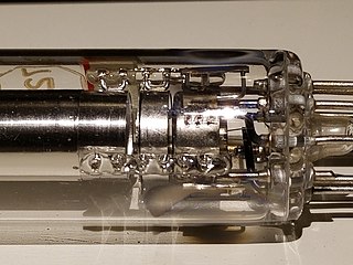
An electron gun is an electrical component in some vacuum tubes that produces a narrow, collimated electron beam that has a precise kinetic energy.

<span class="mw-page-title-main">Tektronix 4010</span> Text and graphics computer terminals

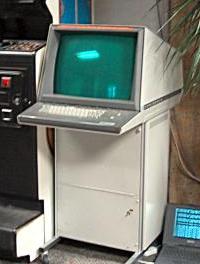
The Tektronix 4010 series was a family of text-and-graphics computer terminals based on storage-tube technology created by Tektronix. Several members of the family were introduced during the 1970s, the best known being the 11-inch 4010 and 19-inch 4014, along with the less popular 25-inch 4016. They were widely used in the computer-aided design market in the 1970s and early 1980s.

<span class="mw-page-title-main">Direct-view bistable storage tube</span>

Direct-view bistable storage tube (DVBST) was an acronym used by Tektronix to describe their line of storage tubes. These were cathode ray tubes (CRT) that stored information written to them using an analog technique inherent in the CRT and based upon the secondary emission of electrons from the phosphor screen itself. The resulting image was visible in the continuously glowing patterns on the face of the CRT.

Cromaclear is a trademark for CRT technology used by NEC during the mid to late-90s. This adopted the slotted shadow mask and in-line electron gun pioneered by the 1966 GE Porta-Color and used by most then-current television tubes to computer monitor use. It was claimed that Cromaclear could offer the image clarity and sharpness of the Trinitron and Diamondtron aperture grille CRTs without the disadvantages e.g. expense and the horizontal damping wires.

The penetron, short for penetration tube, is a type of limited-color television used in some military applications. Unlike a conventional color television, the penetron produces a limited color gamut, typically two colors and their combination. Penetrons, and other military-only cathode ray tubes (CRTs), have been replaced by LCDs in modern designs.

<span class="mw-page-title-main">IMLAC</span> Graphical display system

IMLAC Corporation was an American electronics company in Needham, Massachusetts, that manufactured graphical display systems, mainly, the PDS-1 and PDS-4, in the 1970s.

<span class="mw-page-title-main">Charactron</span>

Charactron was a U.S. registered trademark of Consolidated Vultee Aircraft Corporation (Convair) for its shaped electron beam cathode ray tube. Charactron CRTs performed functions of both a display device and a read-only memory storing multiple characters and fonts. The similar Typotron was a U.S. registered trademark of Hughes Aircraft Corporation for its type of shaped electron beam storage tube with a direct-view bistable storage screen.

<span class="mw-page-title-main">Raster scan</span> Rectangular pattern of image capture and reconstruction

A raster scan, or raster scanning, is the rectangular pattern of image capture and reconstruction in television. By analogy, the term is used for raster graphics, the pattern of image storage and transmission used in most computer bitmap image systems. The word raster comes from the Latin word rastrum, which is derived from radere ; see also rastrum, an instrument for drawing musical staff lines. The pattern left by the lines of a rake, when drawn straight, resembles the parallel lines of a raster: this line-by-line scanning is what creates a raster. It is a systematic process of covering the area progressively, one line at a time. Although often a great deal faster, it is similar in the most general sense to how one's gaze travels when one reads lines of text.

<span class="mw-page-title-main">Vector monitor</span> Type of display device

A vector monitor, vector display, or calligraphic display is a display device used for computer graphics up through the 1970s. It is a type of CRT, similar to that of an early oscilloscope. In a vector display, the image is composed of drawn lines rather than a grid of glowing pixels as in raster graphics. The electron beam follows an arbitrary path, tracing the connected sloped lines rather than following the same horizontal raster path for all images. The beam skips over dark areas of the image without visiting their points.

<span class="mw-page-title-main">Monochrome monitor</span> Type of CRT computer monitor

A monochrome monitor is a type of computer monitor in which computer text and images are displayed in varying tones of only one color, as opposed to a color monitor that can display text and images in multiple colors. They were very common in the early days of computing, from the 1960s through the 1980s, before color monitors became widely commercially available. They are still widely used in applications such as computerized cash register systems, owing to the age of many registers. Green screen was the common name for a monochrome monitor using a green "P1" phosphor screen; the term is often misused to refer to any block mode display terminal, regardless of color, e.g., IBM 3279, 3290.

The beam-index tube is a color television cathode ray tube (CRT) design, using phosphor stripes and active-feedback timing, rather than phosphor dots and a beam-shadowing mask as developed by RCA. Beam indexing offered much brighter pictures than shadow-mask CRTs, reducing power consumption, and as they used a single electron gun rather than three, they were easier to build and required no alignment adjustments.

Electrically operated display devices have developed from electromechanical systems for display of text, up to all-electronic devices capable of full-motion 3D color graphic displays. Electromagnetic devices, using a solenoid coil to control a visible flag or flap, were the earliest type, and were used for text displays such as stock market prices and arrival/departure display times. The cathode ray tube was the workhorse of text and video display technology for several decades until being displaced by plasma, liquid crystal (LCD), and solid-state devices such as thin-film transistors (TFTs), LEDs and OLEDs. With the advent of metal–oxide–semiconductor field-effect transistors (MOSFETs), integrated circuit (IC) chips, microprocessors, and microelectronic devices, many more individual picture elements ("pixels") could be incorporated into one display device, allowing graphic displays and video.

A scotophor is a material showing reversible darkening and bleaching when subjected to certain types of radiation. The name means dark bearer, in contrast to phosphor, which means light bearer. Scotophors show tenebrescence and darken when subjected to an intense radiation such as sunlight. Minerals showing such behavior include hackmanite sodalite, spodumene and tugtupite. Some pure alkali halides also show such behavior.

This is a subdivision of the Oscilloscope article, discussing the various types and models of oscilloscopes in greater detail.

<span class="mw-page-title-main">History of the oscilloscope</span>


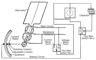
The history of the oscilloscope was fundamental to science because an oscilloscope is a device for viewing waveform oscillations, as of electrical voltage or current, in order to measure frequency and other wave characteristics. This was important in developing electromagnetic theory. The first recordings of waveforms were with a galvanometer coupled to a mechanical drawing system dating from the second decade of the 19th century. The modern day digital oscilloscope is a consequence of multiple generations of development of the oscillograph, cathode-ray tubes, analog oscilloscopes, and digital electronics.

<span class="mw-page-title-main">Deflection yoke</span> Part of a cathode ray tube which moves the electron beam around

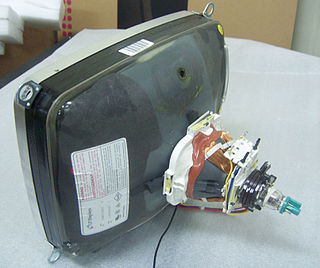
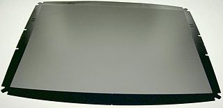
A deflection yoke is a kind of magnetic lens, used in cathode ray tubes to scan the electron beam both vertically and horizontally over the whole screen.

References

  1. PROGRAMMED DATA PROCESSOR-1 HANDBOOK (PDF). Maynard Massachusetts: Digital Equipment Corporation. 1963. p. 34. Retrieved 21 August 2023.
  2. "Computer Display Review", Keydata Corp., March 1970, pp. V.1980, V.1964 Archived at the Wayback Machine
  3. Michael L. Dertouzos (April 1967). "Phaseplot: An On-Line Graphical Display Technique". IEEE Transactions on Electronic Computers. IEEE. EC-16 (2): 203–209. doi:10.1109/pgec.1967.264817. The main advantage of this technique is graphical data compression.
  4. Michael L. Dertouzos (April 1967). "Phaseplot: An On-Line Graphical Display Technique". IEEE Transactions on Electronic Computers. IEEE. EC-16 (2): 203–209. doi:10.1109/pgec.1967.264817. This article describes the principle used in the graphical output portion of the Computek series 400 Display Terminals (added to a reprint of the article distributed by Computek)