In electronics, the figures of merit of an amplifier are numerical measures that characterize its properties and performance. Figures of merit can be given as a list of specifications that include properties such as gain, bandwidth, noise and linearity, among others listed in this article. Figures of merit are important for determining the suitability of a particular amplifier for an intended use.
An electronic oscillator is an electronic circuit that produces a periodic, oscillating or alternating current (AC) signal, usually a sine wave, square wave or a triangle wave, powered by a direct current (DC) source. Oscillators are found in many electronic devices, such as radio receivers, television sets, radio and television broadcast transmitters, computers, computer peripherals, cellphones, radar, and many other devices.

An amplifier, electronic amplifier or (informally) amp is an electronic device that can increase the magnitude of a signal. It is a two-port electronic circuit that uses electric power from a power supply to increase the amplitude of a signal applied to its input terminals, producing a proportionally greater amplitude signal at its output. The amount of amplification provided by an amplifier is measured by its gain: the ratio of output voltage, current, or power to input. An amplifier is defined as a circuit that has a power gain greater than one.

Microwave is a form of electromagnetic radiation with wavelengths ranging from about 30 centimeters to one millimeter corresponding to frequencies between 1 GHz and 300 GHz respectively. Different sources define different frequency ranges as microwaves; the above broad definition includes UHF, SHF and EHF bands. A more common definition in radio-frequency engineering is the range between 1 and 100 GHz. In all cases, microwaves include the entire SHF band at minimum. Frequencies in the microwave range are often referred to by their IEEE radar band designations: S, C, X, Ku, K, or Ka band, or by similar NATO or EU designations.
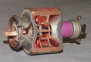
The cavity magnetron is a high-power vacuum tube used in early radar systems and subsequently in microwave ovens and in linear particle accelerators. A cavity magnetron generates microwaves using the interaction of a stream of electrons with a magnetic field, while moving past a series of cavity resonators, which are small, open cavities in a metal block. Electrons pass by the cavities and cause microwaves to oscillate within, similar to the functioning of a whistle producing a tone when excited by an air stream blown past its opening. The resonant frequency of the arrangement is determined by the cavities' physical dimensions. Unlike other vacuum tubes, such as a klystron or a traveling-wave tube (TWT), the magnetron cannot function as an amplifier for increasing the intensity of an applied microwave signal; the magnetron serves solely as an electronic oscillator generating a microwave signal from direct current electricity supplied to the vacuum tube.

A vacuum tube, electron tube, valve, or tube, is a device that controls electric current flow in a high vacuum between electrodes to which an electric potential difference has been applied.
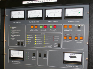
In electronics and telecommunications, a radio transmitter or just transmitter is an electronic device which produces radio waves with an antenna. The transmitter itself generates a radio frequency alternating current, which is applied to the antenna. When excited by this alternating current, the antenna radiates radio waves.
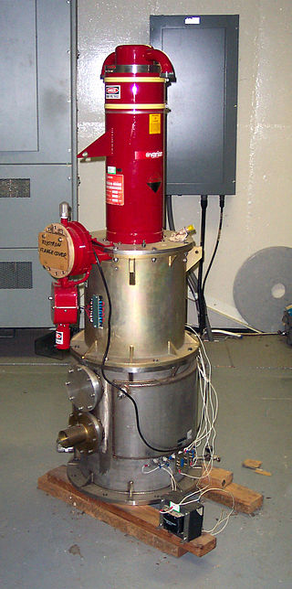
A klystron is a specialized linear-beam vacuum tube, invented in 1937 by American electrical engineers Russell and Sigurd Varian, which is used as an amplifier for high radio frequencies, from UHF up into the microwave range. Low-power klystrons are used as oscillators in terrestrial microwave relay communications links, while high-power klystrons are used as output tubes in UHF television transmitters, satellite communication, radar transmitters, and to generate the drive power for modern particle accelerators.

A traveling-wave tube or traveling-wave tube amplifier is a specialized vacuum tube that is used in electronics to amplify radio frequency (RF) signals in the microwave range. It was invented by Andrei Haeff around 1933 as a graduate student at Caltech, and its present form was invented by Rudolf Kompfner in 1942-43. The TWT belongs to a category of "linear beam" tubes, such as the klystron, in which the radio wave is amplified by absorbing power from a beam of electrons as it passes down the tube. Although there are various types of TWT, two major categories are:

A Gunn diode, also known as a transferred electron device (TED), is a form of diode, a two-terminal semiconductor electronic component, with negative resistance, used in high-frequency electronics. It is based on the "Gunn effect" discovered in 1962 by physicist J. B. Gunn. Its main uses are in electronic oscillators to generate microwaves, in applications such as radar speed guns, microwave relay data link transmitters, and automatic door openers.
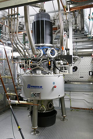
A gyrotron is a class of high-power linear-beam vacuum tubes that generates millimeter-wave electromagnetic waves by the cyclotron resonance of electrons in a strong magnetic field. Output frequencies range from about 20 to 527 GHz, covering wavelengths from microwave to the edge of the terahertz gap. Typical output powers range from tens of kilowatts to 1–2 megawatts. Gyrotrons can be designed for pulsed or continuous operation. The gyrotron was invented by Soviet scientists at NIRFI, based in Nizhny Novgorod, Russia.

A backward wave oscillator (BWO), also called carcinotron or backward wave tube, is a vacuum tube that is used to generate microwaves up to the terahertz range. Belonging to the traveling-wave tube family, it is an oscillator with a wide electronic tuning range.
A radio transmitter or just transmitter is an electronic device which produces radio waves with an antenna. Radio waves are electromagnetic waves with frequencies between about 30 Hz and 300 GHz. The transmitter itself generates a radio frequency alternating current, which is applied to the antenna. When excited by this alternating current, the antenna radiates radio waves. Transmitters are necessary parts of all systems that use radio: radio and television broadcasting, cell phones, wireless networks, radar, two way radios like walkie talkies, radio navigation systems like GPS, remote entry systems, among numerous other uses.

Distributed amplifiers are circuit designs that incorporate transmission line theory into traditional amplifier design to obtain a larger gain-bandwidth product than is realizable by conventional circuits.
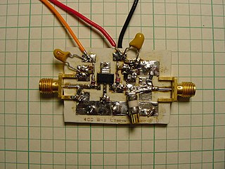
A radio-frequency power amplifier is a type of electronic amplifier that converts a low-power radio-frequency (RF) signal into a higher-power signal. Typically, RF power amplifiers are used in the final stage of a radio transmitter, their output driving the antenna. Design goals often include gain, power output, bandwidth, power efficiency, linearity, input and output impedance matching, and heat dissipation.
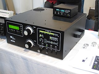
A valve RF amplifier or tube amplifier (U.S.) is a device for electrically amplifying the power of an electrical radio frequency signal.
The inductive output tube (IOT) or klystrode is a variety of linear-beam vacuum tube, similar to a klystron, used as a power amplifier for high frequency radio waves. It evolved in the 1980s to meet increasing efficiency requirements for high-power RF amplifiers in radio transmitters. The primary commercial use of IOTs is in UHF television transmitters, where they have mostly replaced klystrons because of their higher efficiencies and smaller size. IOTs are also used in particle accelerators. They are capable of producing power output up to about 30 kW continuous and 7 MW pulsed and gains of 20–23 dB at frequencies up to about a gigahertz.
A microwave power module (MPM) is a microwave device used to amplify radio frequency signals to high power levels. It is a hybrid combination of solid-state and vacuum tube electronics, which encloses a solid-state driver amplifier (SSPA), traveling wave tube amplifier (TWTA) and electronic power conditioning (EPC) modules into a single unit. Their average output power capability falls between that of solid-state power amplifiers (SSPAs) and dedicated Traveling Wave Tube (TWT) amplifiers. They may be applied wherever high power microwave amplification is required, and space is at a premium. They are available in various frequency ranges, from S band up to W band. Typical output power at Ku band ranges from 20W to 1 kW.

Sutton tube was the name given to the first reflex klystron, developed in 1940 by Robert W. Sutton of Signal School group at the Bristol University. The Sutton tube was developed as a local oscillator for the receiver of 10cm microwave radar sets. Due to its geometry and long drift space, it suffered from mode jumping through the tuning range. For this reason, from late 1941 onward, it was replaced in many sets by the Western Electric 707A.

The extended interaction oscillator (EIO) is a linear-beam vacuum tube designed to convert direct current to RF power. The conversion mechanism is the space charge wave process whereby velocity modulation in an electron beam transforms to current or density modulation with distance.