
A rectifier is an electrical device that converts alternating current (AC), which periodically reverses direction, to direct current (DC), which flows in only one direction. The reverse operation is performed by the inverter.

A power inverter, or inverter, is a power electronic device or circuitry that changes direct current (DC) to alternating current (AC). The resulting AC frequency obtained depends on the particular device employed. Inverters do the opposite of “converters” which were originally large electromechanical devices converting AC to DC.
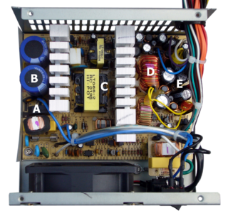
A switched-mode power supply is an electronic power supply that incorporates a switching regulator to convert electrical power efficiently.

The Ćuk converter is a type of DC/DC converter that has an output voltage magnitude that is either greater than or less than the input voltage magnitude. It is essentially a boost converter followed by a buck converter with a capacitor to couple the energy.
A DC-to-DC converter is an electronic circuit or electromechanical device that converts a source of direct current (DC) from one voltage level to another. It is a type of electric power converter. Power levels range from very low to very high.

Power electronics is the application of solid-state electronics to the control and conversion of electric power.
A voltage doubler is an electronic circuit which charges capacitors from the input voltage and switches these charges in such a way that, in the ideal case, exactly twice the voltage is produced at the output as at its input.

A variable-frequency drive (VFD) or adjustable-frequency drive (AFD), variable-voltage/variable-frequency (VVVF) drive, variable speed drive (VSD), AC drive, micro drive or inverter drive is a type of motor drive used in electro-mechanical drive systems to control AC motor speed and torque by varying motor input frequency and voltage.
A boost converter is a DC-to-DC power converter that steps up voltage from its input (supply) to its output (load). It is a class of switched-mode power supply (SMPS) containing at least two semiconductors and at least one energy storage element: a capacitor, inductor, or the two in combination. To reduce voltage ripple, filters made of capacitors are normally added to such a converter's output and input.
A buck converter is a DC-to-DC power converter which steps down voltage from its input (supply) to its output (load). It is a class of switched-mode power supply (SMPS) typically containing at least two semiconductors and at least one energy storage element, a capacitor, inductor, or the two in combination. To reduce voltage ripple, filters made of capacitors are normally added to such a converter's output and input.
The buck–boost converter is a type of DC-to-DC converter that has an output voltage magnitude that is either greater than or less than the input voltage magnitude. It is equivalent to a flyback converter using a single inductor instead of a transformer.
An H-bridge is an electronic circuit that switches the polarity of a voltage applied to a load. These circuits are often used in robotics and other applications to allow DC motors to run forwards or backwards.

A push–pull converter is a type of DC-to-DC converter, a switching converter that uses a transformer to change the voltage of a DC power supply. The distinguishing feature of a push-pull converter is that the transformer primary is supplied with current from the input line by pairs of transistors in a symmetrical push-pull circuit. The transistors are alternately switched on and off, periodically reversing the current in the transformer. Therefore, current is drawn from the line during both halves of the switching cycle. This contrasts with buck-boost converters, in which the input current is supplied by a single transistor which is switched on and off, so current is only drawn from the line during half the switching cycle. During the other half the output power is supplied by energy stored in inductors or capacitors in the power supply. Push–pull converters have steadier input current, create less noise on the input line, and are more efficient in higher power applications.

The flyback converter is used in both AC/DC and DC/DC conversion with galvanic isolation between the input and any outputs. The flyback converter is a buck-boost converter with the inductor split to form a transformer, so that the voltage ratios are multiplied with an additional advantage of isolation. When driving for example a plasma lamp or a voltage multiplier the rectifying diode of the boost converter is left out and the device is called a flyback transformer.

The single-ended primary-inductor converter (SEPIC) is a type of DC/DC converter that allows the electrical potential (voltage) at its output to be greater than, less than, or equal to that at its input. The output of the SEPIC is controlled by the duty cycle of the control switch (S1).

Active rectification, or synchronous rectification, is a technique for improving the efficiency of rectification by replacing diodes with actively controlled switches, usually power MOSFETs or power BJTs. Whereas normal semiconductor diodes have a roughly fixed voltage drop of around 0.5-1 volts, active rectifiers behave as resistances, and can have arbitrarily low voltage drop.
The Sparse Matrix Converter is an AC/AC converter which offers a reduced number of components, a low-complexity modulation scheme, and low realization effort. Invented in 2001 by Prof Johann W. Kolar , sparse matrix converters avoid the multi step commutation procedure of the conventional matrix converter, improving system reliability in industrial operations. Its principal application is in highly compact integrated AC drives.
A gate driver is a power amplifier that accepts a low-power input from a controller IC and produces a high-current drive input for the gate of a high-power transistor such as an IGBT or power MOSFET. Gate drivers can be provided either on-chip or as a discrete module. In essence, a gate driver consists of a level shifter in combination with an amplifier. A gate driver IC serves as the interface between control signals and power switches. An integrated gate-driver solution reduces design complexity, development time, bill of materials (BOM), and board space while improving reliability over discretely-implemented gate-drive solutions.
A Z-source inverter is a type of power inverter, a circuit that converts direct current to alternating current. It functions as a buck-boost inverter without making use of DC-DC converter bridge due to its unique circuit topology.
Slobodan Ćuk is a Serbian American author, inventor, business owner, electrical engineer, and professor of electrical engineering at the California Institute of Technology (Caltech). The Ćuk switched-mode DC-to-DC voltage converter is named after Slobodan Ćuk.
