Time base generator

Last updated

A time base generator (also timebase or time base) is a special type of function generator, an electronic circuit that generates a varying voltage to produce a particular waveform. Time base generators produce very high frequency sawtooth waves specifically designed to deflect the beam of a cathode ray tube (CRT) smoothly across the face of the tube and then return it to its starting position.

Contents

Time bases are used by radar systems to determine range to a target, by comparing the current location along the time base to the time of arrival of radio echoes. Analog television systems using CRTs had two time bases, one for deflecting the beam horizontally in a rapid movement, and another pulling it down the screen 60 times per second. Oscilloscopes often have several time bases, but these may be more flexible function generators able to produce many waveforms as well as a simple time base.

Description

A basic oscilloscope typically employs a time base generator, which is controlled with the top dial, while the bottom dial controls the amplification of the signal. Oscilloscope diagram.svg
A basic oscilloscope typically employs a time base generator, which is controlled with the top dial, while the bottom dial controls the amplification of the signal.

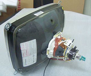
A cathode ray tube (CRT) consists of three primary parts, the electron gun that provides a stream of accelerated electrons, the phosphor-covered screen that lights up when the electrons hit it, and the deflection plates that use magnetic or electric fields to deflect the electrons in-flight and allows them to be directed around the screen. It is the ability for the electron stream to be rapidly moved using the deflection plates that allows the CRT to be used to display very rapid signals, like those of a television signal or to be used for radio direction finding (see huff-duff).

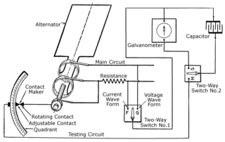
Many signals of interest vary over time at a very rapid rate, but have an underlying periodic nature. Radio signals, for instance, have a base frequency, the carrier, which forms the basis for the signal. Sounds are modulated into the carrier by modifying the signal, either in amplitude (AM), frequency (FM) or similar techniques. To display such a signal on an oscilloscope for examination, it is desirable to have the electron beam sweep across the screen so that the electron beam cycles at the same frequency as the carrier, or some multiple of that base frequency.

This is the purpose of the time base generator, which is attached to one of the set of deflection plates, normally the X axis, while the amplified output of the radio signal is sent to the other axis, normally Y. The result is a visual re-creation of the original waveform.

Use in radar

A typical radar system broadcasts a short pulse of radio signal and then listens for echoes from distant objects. As the signal travels at the speed of light and has to travel to the target object and back, the distance to the target can be determined by measuring the delay between the broadcast and reception, multiplying the speed of light by that time, and then dividing by two (there and back again). As this process occurs very rapidly, a CRT is used to display the signal and look for the echoes.

In the simplest version of a radar display, today known as an "A-scope", a time base generator sweeps the display across the screen so that it reaches one side at the time when the signal has travelled the radar's maximum effective distance. For instance, an early warning radar like Chain Home (CH) might have a maximum range of 150 kilometres (93 mi), a distance that light will travel out and back in 1 millisecond. This would be used with a time base generator that pulls the beam across the CRT once every millisecond, starting the sweep when the broadcast signal ends. Any echoes cause the beam to deflect down (in the case of CH) as it moves across the display.

By measuring the physical location of the "blip" on the CRT, one can determine the range to the target. For instance, if a particular radar has a time base of 1 millisecond, then its maximum range is 150 km. If this is displayed on a four-inch CRT and the blip is measured to be 2 inches from the left side, then the target is 0.5 milliseconds away, or about 75 kilometres (47 mi).

To ensure the blips would line up properly with a mechanical scale, the time base could be adjusted to start its sweep at a certain time. This could be adjusted manually, or automatically trigged by another signal, normally a greatly attenuated version of the broadcast signal.

Later systems modified the time base to include a second signal that periodically produced blips on the display, providing a clock signal that varied with the time base and thus did not need to be aligned. In UK terminology, these were known as strobes.

Use in television

Television signals consist of a series of still images broadcast in sequence, in the NTSC standard such a "frame" is broadcast 30 times a second. Each frame is itself broken down into a series of "lines", 525 in the NTSC standard. If one examines a television broadcast on an oscilloscope, it will appear to be a continual sequence of modulated signals broken up by short periods of "empty" signal. Each modulated portion carries the analog image for a single line.

To display the signal, two time bases are used. One sweeps the beam horizontally from left to right at 15,750 times a second, the time it takes for one line to be sent. A second time base causes the beam to scan down the screen 60 times a second, so that each line appears below the last one drawn and then returns to the top. This causes the entire signal of 525 lines to be drawn down the screen, re-creating a 2-dimensional image.

To ensure the time base began its sweep of the screen at the right time, the signal included several special modulations. With each line there was a brief period, the "front porch" and "back porch" that caused the signal to go negative briefly. This triggered the horizontal time base to start its sweep across the screen, ensuring that the lines started on the left of the display. A much longer but otherwise similar signal, the vertical blanking interval caused the vertical time base to start, with any lengthy delay causing the time base to trigger.

Related Research Articles

<span class="mw-page-title-main">Analog television</span> Television that uses analog signals

Analog television is the original television technology that uses analog signals to transmit video and audio. In an analog television broadcast, the brightness, colors and sound are represented by amplitude, phase and frequency of an analog signal.

<span class="mw-page-title-main">Cathode-ray tube</span> Vacuum tube manipulated to display images on a phosphorescent screen

A cathode-ray tube (CRT) is a vacuum tube containing one or more electron guns, which emit electron beams that are manipulated to display images on a phosphorescent screen. The images may represent electrical waveforms (oscilloscope), pictures, radar targets, or other phenomena. A CRT on a television set is commonly called a picture tube. CRTs have also been used as memory devices, in which case the screen is not intended to be visible to an observer. The term cathode ray was used to describe electron beams when they were first discovered, before it was understood that what was emitted from the cathode was a beam of electrons.

<span class="mw-page-title-main">Sawtooth wave</span> Non-sinusoidal waveform

The sawtooth wave is a kind of non-sinusoidal waveform. It is so named based on its resemblance to the teeth of a plain-toothed saw with a zero rake angle. A single sawtooth, or an intermittently triggered sawtooth, is called a ramp waveform.

<span class="mw-page-title-main">Vectorscope</span>

A Vectorscope is a special type of oscilloscope used in both audio and video applications. Whereas an oscilloscope or waveform monitor normally displays a plot of signal vs. time, a vectorscope displays an X-Y plot of two signals, which can reveal details about the relationship between these two signals. Vectorscopes are highly similar in operation to oscilloscopes operated in X-Y mode; however those used in video applications have specialized graticules, and accept standard television or video signals as input.

<span class="mw-page-title-main">Storage tube</span>

Storage tubes are a class of cathode-ray tubes (CRTs) that are designed to hold an image for a long period of time, typically as long as power is supplied to the tube.

Gee-H, sometimes written G-H or GEE-H, was a radio navigation system developed by Britain during World War II to aid RAF Bomber Command. The name refers to the system's use of the earlier Gee equipment, as well as its use of the "H principle" or "twin-range principle" of location determination. Its official name was AMES Type 100.

Horizontal blanking interval refers to a part of the process of displaying images on a computer monitor or television screen via raster scanning. CRT screens display images by moving beams of electrons very quickly across the screen. Once the beam of the monitor has reached the edge of the screen, it is switched off, and the deflection circuit voltages are returned to the values they had for the other edge of the screen; this would have the effect of retracing the screen in the opposite direction, so the beam is turned off during this time. This part of the line display process is the Horizontal Blank.

The penetron, short for penetration tube, is a type of limited-color television used in some military applications. Unlike a conventional color television, the penetron produces a limited color gamut, typically two colors and their combination. Penetrons, and other military-only cathode ray tubes (CRTs), have been replaced by LCDs in modern designs.

<span class="mw-page-title-main">Charactron</span>

Charactron was a U.S. registered trademark of Consolidated Vultee Aircraft Corporation (Convair) for its shaped electron beam cathode ray tube. Charactron CRTs performed functions of both a display device and a read-only memory storing multiple characters and fonts. The similar Typotron was a U.S. registered trademark of Hughes Aircraft Corporation for its type of shaped electron beam storage tube with a direct-view bistable storage screen.

<span class="mw-page-title-main">Raster scan</span> Rectangular pattern of image capture and reconstruction

A raster scan, or raster scanning, is the rectangular pattern of image capture and reconstruction in television. By analogy, the term is used for raster graphics, the pattern of image storage and transmission used in most computer bitmap image systems. The word raster comes from the Latin word rastrum, which is derived from radere ; see also rastrum, an instrument for drawing musical staff lines. The pattern left by the lines of a rake, when drawn straight, resembles the parallel lines of a raster: this line-by-line scanning is what creates a raster. It is a systematic process of covering the area progressively, one line at a time. Although often a great deal faster, it is similar in the most general sense to how one's gaze travels when one reads lines of text.

<span class="mw-page-title-main">Radar display</span> Electronic device

A radar display is an electronic device to present radar data to the operator. The radar system transmits pulses or continuous waves of electromagnetic radiation, a small portion of which backscatter off targets and return to the radar system. The receiver converts all received electromagnetic radiation into a continuous electronic analog signal of varying voltage that can be converted then to a screen display.

<span class="mw-page-title-main">Vector monitor</span> Type of display device

A vector monitor, vector display, or calligraphic display is a display device used for computer graphics up through the 1970s. It is a type of CRT, similar to that of an early oscilloscope. In a vector display, the image is composed of drawn lines rather than a grid of glowing pixels as in raster graphics. The electron beam follows an arbitrary path tracing the connected sloped lines, rather than following the same horizontal raster path for all images. The beam skips over dark areas of the image without visiting their points.

In radar systems, the blip-to-scan ratio, or blip/scan, is the ratio of the number of times a target appears on a radar display to the number of times it theoretically could be displayed. Alternately it can be defined as the ratio of the number of scans in which an accurate return is received to the total number of scans.

<span class="mw-page-title-main">Oscilloscope</span> Instrument for displaying time-varying signals

An oscilloscope is a type of electronic test instrument that graphically displays varying electrical voltages as a two-dimensional plot of one or more signals as a function of time. The main purposes are to display repetitive or single waveforms on the screen that would otherwise occur too briefly to be perceived by the human eye. The displayed waveform can then be analyzed for properties such as amplitude, frequency, rise time, time interval, distortion, and others. Originally, calculation of these values required manually measuring the waveform against the scales built into the screen of the instrument. Modern digital instruments may calculate and display these properties directly.

This is a subdivision of the Oscilloscope article, discussing the various types and models of oscilloscopes in greater detail.

<span class="mw-page-title-main">History of the oscilloscope</span>


The history of the oscilloscope was fundamental to science because an oscilloscope is a device for viewing waveform oscillations, as of electrical voltage or current, in order to measure frequency and other wave characteristics. This was important in developing electromagnetic theory. The first recordings of waveforms were with a galvanometer coupled to a mechanical drawing system dating from the second decade of the 19th century. The modern day digital oscilloscope is a consequence of multiple generations of development of the oscillograph, cathode-ray tubes, analog oscilloscopes, and digital electronics.

Tektronix vintage analog oscilloscopes technologies and evolution. The company was founded in the mid-1940s to produce oscilloscopes.

<span class="mw-page-title-main">Beam deflection tube</span> Vacuum tube with an electron beam deflectable to one of two anodes

Beam deflection tubes, sometimes known as sheet beam tubes, are vacuum tubes with an electron gun, a beam intensity control grid, a screen grid, sometimes a suppressor grid, and two electrostatic deflection electrodes on opposite sides of the electron beam that can direct the rectangular beam to either of two anodes in the same plane.

<span class="mw-page-title-main">GL Mk. I radar</span>

Radar, Gun Laying, Mark I, or GL Mk. I for short, was an early radar system developed by the British Army to provide range information to associated anti-aircraft artillery. There were two upgrades to the same basic system, GL/EF and GL Mk. II, both of which added the ability to accurately determine bearing and elevation.

<span class="mw-page-title-main">Deflection yoke</span> Part of a cathode ray tube which moves the electron beam around

A deflection yoke is a kind of magnetic lens, used in cathode ray tubes to scan the electron beam both vertically and horizontally over the whole screen.

References