
Transistor testers are instruments for testing the electrical behavior of transistors and solid-state diodes. [1]
Transistor testers are instruments for testing the electrical behavior of transistors and solid-state diodes. [1]
There are three types of transistor testers each performing a unique operation.
In addition, curve tracers are reliable indicators of transistor performance.
A circuit tester is used to check whether a transistor which has previously been performing properly in a circuit is still operational. The transistor's ability to "amplify" is taken as a rough index of its performance. This type of tester indicates to a technician whether the transistor is dead or still operative. The advantage of this tester is that the transistor does not have to be removed from the circuit.
These devices usually perform three types of checks:
Some service testers include a go/no-go feature, indicating a pass when a certain hfe is exceeded. These are useful, but fail some functional but low hfe transistors.
Some also provide a means of identifying transistor elements, if these are unknown. The tester has all these features and can check solid-state devices in and out of circuit.
Transistor hfe varies fairly widely with Ic, so measurements with the service type tester give readings that can differ quite a bit from the hfe in the transistor's real life application. Hence these testers are useful, but can't be regarded as giving accurate real-life hfe values.
This type of tester is used for measuring transistor parameters dynamically under various operating conditions. The readings they give are absolute. Among the important characteristics measured are:
Transistor testers have the necessary controls and switches for making the proper voltage, current and signal settings. A meter with a calibrated "good" and "bad" scale is on the front. In addition, these transistor testers are designed to check the solid-state diodes. There are also testers for checking high transistor and rectifiers.

An amplifier, electronic amplifier or (informally) amp is an electronic device that can increase the magnitude of a signal. It is a two-port electronic circuit that uses electric power from a power supply to increase the amplitude of a signal applied to its input terminals, producing a proportionally greater amplitude signal at its output. The amount of amplification provided by an amplifier is measured by its gain: the ratio of output voltage, current, or power to input. An amplifier is defined as a circuit that has a power gain greater than one.

A transistor is a semiconductor device used to amplify or switch electrical signals and power. It is one of the basic building blocks of modern electronics. It is composed of semiconductor material, usually with at least three terminals for connection to an electronic circuit. A voltage or current applied to one pair of the transistor's terminals controls the current through another pair of terminals. Because the controlled (output) power can be higher than the controlling (input) power, a transistor can amplify a signal. Some transistors are packaged individually, but many more in miniature form are found embedded in integrated circuits. Because transistors are the key active components in practically all modern electronics, many people consider them one of the 20th century's greatest inventions.
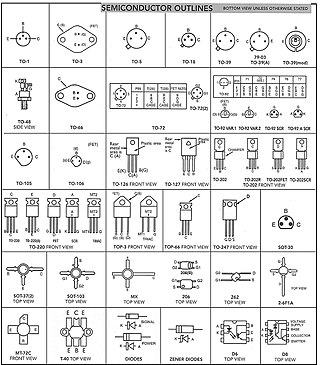
A semiconductor device is an electronic component that relies on the electronic properties of a semiconductor material for its function. Its conductivity lies between conductors and insulators. Semiconductor devices have replaced vacuum tubes in most applications. They conduct electric current in the solid state, rather than as free electrons across a vacuum or as free electrons and ions through an ionized gas.
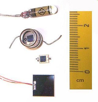
A photodiode is a semiconductor diode sensitive to photon radiation, such as visible light, infrared or ultraviolet radiation, X-rays and gamma rays. It produces an electrical current when it absorbs photons. This can be used for detection and measurement applications, or for the generation of electrical power in solar cells. Photodiodes are used in a wide range of applications throughout the electromagnetic spectrum from visible light photocells to gamma ray spectrometers.
Transistor–transistor logic (TTL) is a logic family built from bipolar junction transistors. Its name signifies that transistors perform both the logic function and the amplifying function, as opposed to earlier resistor–transistor logic (RTL) and diode–transistor logic (DTL).
A bipolar junction transistor (BJT) is a type of transistor that uses both electrons and electron holes as charge carriers. In contrast, a unipolar transistor, such as a field-effect transistor (FET), uses only one kind of charge carrier. A bipolar transistor allows a small current injected at one of its terminals to control a much larger current flowing between the terminals, making the device capable of amplification or switching.

A Zener diode is a special type of diode designed to reliably allow current to flow "backwards" when a certain set reverse voltage, known as the Zener voltage, is reached.
A unijunction transistor (UJT) is a three-lead electronic semiconductor device with only one junction. It acts exclusively as an electrically controlled switch.
In electronics, a Darlington configuration is a circuit consisting of two bipolar transistors with the emitter of one transistor connected to the base of the other, such that the current amplified by the first transistor is amplified further by the second one. The collectors of both transistors are connected together. This configuration has a much higher current gain than each transistor taken separately. It acts like and is often packaged as a single transistor. It was invented in 1953 by Sidney Darlington.
Resistor–transistor logic (RTL), sometimes also known as transistor–resistor logic (TRL), is a class of digital circuits built using resistors as the input network and bipolar junction transistors (BJTs) as switching devices. RTL is the earliest class of transistorized digital logic circuit; it was succeeded by diode–transistor logic (DTL) and transistor–transistor logic (TTL).
A current mirror is a circuit designed to copy a current through one active device by controlling the current in another active device of a circuit, keeping the output current constant regardless of loading. The current being "copied" can be, and sometimes is, a varying signal current. Conceptually, an ideal current mirror is simply an ideal inverting current amplifier that reverses the current direction as well, or it could consist of a current-controlled current source (CCCS). The current mirror is used to provide bias currents and active loads to circuits. It can also be used to model a more realistic current source.

A current source is an electronic circuit that delivers or absorbs an electric current which is independent of the voltage across it.

The breakdown voltage of an insulator is the minimum voltage that causes a portion of an insulator to experience electrical breakdown and become electrically conductive.

An electronic component is any basic discrete electronic device or physical entity part of an electronic system used to affect electrons or their associated fields. Electronic components are mostly industrial products, available in a singular form and are not to be confused with electrical elements, which are conceptual abstractions representing idealized electronic components and elements. A datasheet for an electronic component is a technical document that provides detailed information about the component's specifications, characteristics, and performance. Discrete circuits are made of individual electronic components that only perform one function each as packaged, which are known as discrete components, although strictly the term discrete component refers to such a component with semiconductor material such as individual transistors.
An avalanche transistor is a bipolar junction transistor designed for operation in the region of its collector-current/collector-to-emitter voltage characteristics beyond the collector-to-emitter breakdown voltage, called avalanche breakdown region. This region is characterized by avalanche breakdown, which is a phenomenon similar to Townsend discharge for gases, and negative differential resistance. Operation in the avalanche breakdown region is called avalanche-mode operation: it gives avalanche transistors the ability to switch very high currents with less than a nanosecond rise and fall times. Transistors not specifically designed for the purpose can have reasonably consistent avalanche properties; for example 82% of samples of the 15V high-speed switch 2N2369, manufactured over a 12-year period, were capable of generating avalanche breakdown pulses with rise time of 350 ps or less, using a 90V power supply as Jim Williams writes.
A Wilson current mirror is a three-terminal circuit that accepts an input current at the input terminal and provides a "mirrored" current source or sink output at the output terminal. The mirrored current is a precise copy of the input current. It may be used as a Wilson current source by applying a constant bias current to the input branch as in Fig. 2. The circuit is named after George R. Wilson, an integrated circuit design engineer who worked for Tektronix. Wilson devised this configuration in 1967 when he and Barrie Gilbert challenged each other to find an improved current mirror overnight that would use only three transistors. Wilson won the challenge.

The 2N2222 is a common NPN bipolar junction transistor (BJT) used for general purpose low-power amplifying or switching applications. It is designed for low to medium current, low power, medium voltage, and can operate at moderately high speeds. It was originally made in the TO-18 metal can as shown in the picture.

In graphical analysis of nonlinear electronic circuits, a load line is a line drawn on the current–voltage characteristic graph for a nonlinear device like a diode or transistor. It represents the constraint put on the voltage and current in the nonlinear device by the external circuit. The load line, usually a straight line, represents the response of the linear part of the circuit, connected to the nonlinear device in question. The points where the characteristic curve and the load line intersect are the possible operating point(s) of the circuit; at these points the current and voltage parameters of both parts of the circuit match.

Bipolar transistors must be properly biased to operate correctly. In circuits made with individual devices, biasing networks consisting of resistors are commonly employed. Much more elaborate biasing arrangements are used in integrated circuits, for example, bandgap voltage references and current mirrors. The voltage divider configuration achieves the correct voltages by the use of resistors in certain patterns. By selecting the proper resistor values, stable current levels can be achieved that vary only little over temperature and with transistor properties such as β.

A tube tester is an electronic instrument designed to test certain characteristics of vacuum tubes. Tube testers evolved along with the vacuum tube to satisfy the demands of the time, and their evolution ended with the tube era. The first tube testers were simple units designed for specific tubes to be used in the battlefields of World War I by radio operators, so they could easily test the tubes of their communication equipment.