
Digital electronics is a field of electronics involving the study of digital signals and the engineering of devices that use or produce them. This is in contrast to analog electronics which work primarily with analog signals. Despite the name, digital electronics designs includes important analog design considerations.

In electronics, a comparator is a device that compares two voltages or currents and outputs a digital signal indicating which is larger. It has two analog input terminals and and one binary digital output . The output is ideally
A signal generator is one of a class of electronic devices that generates electrical signals with set properties of amplitude, frequency, and wave shape. These generated signals are used as a stimulus for electronic measurements, typically used in designing, testing, troubleshooting, and repairing electronic or electroacoustic devices, though it often has artistic uses as well.
Transistor–transistor logic (TTL) is a logic family built from bipolar junction transistors. Its name signifies that transistors perform both the logic function and the amplifying function, as opposed to earlier resistor–transistor logic (RTL) and diode–transistor logic (DTL).

Modular synthesizers are synthesizers composed of separate modules for different functions. The modules can be connected together by the user to create a patch. The outputs from the modules may include audio signals, analog control voltages, or digital signals for logic or timing conditions. Typical modules are voltage-controlled oscillators, voltage-controlled filters, voltage-controlled amplifiers and envelope generators.

Electronic test equipment is used to create signals and capture responses from electronic devices under test (DUTs). In this way, the proper operation of the DUT can be proven or faults in the device can be traced. Use of electronic test equipment is essential to any serious work on electronics systems.
This is an index of articles relating to electronics and electricity or natural electricity and things that run on electricity and things that use or conduct electricity.

CV/gate is an analog method of controlling synthesizers, drum machines, and similar equipment with external sequencers. The control voltage typically controls pitch and the gate signal controls note on-off.
Differential TTL is a type of binary electrical signaling based on the transistor-transistor logic (TTL) concept. It enables electronic systems to be relatively immune to noise. RS-422 and RS-485 outputs can be implemented as differential TTL.
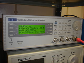
In electrical engineering, a function generator is usually a piece of electronic test equipment or software used to generate different types of electrical waveforms over a wide range of frequencies. Some of the most common waveforms produced by the function generator are the sine wave, square wave, triangular wave and sawtooth shapes. These waveforms can be either repetitive or single-shot. Another feature included on many function generators is the ability to add a DC offset. Integrated circuits used to generate waveforms may also be described as function generator ICs.

A pulse generator is either an electronic circuit or a piece of electronic test equipment used to generate rectangular pulses. Pulse generators are used primarily for working with digital circuits; related function generators are used primarily for analog circuits.

An arbitrary waveform generator (AWG) is a piece of electronic test equipment used to generate electrical waveforms. These waveforms can be either repetitive or single-shot in which case some kind of triggering source is required. The resulting waveforms can be injected into a device under test and analyzed as they progress through it, confirming the proper operation of the device or pinpointing a fault in it.
A video signal generator is a type of signal generator which outputs predetermined video and/or television oscillation waveforms, and other signals used in the synchronization of television devices and to stimulate faults in, or aid in parametric measurements of, television and video systems. There are several different types of video signal generators in widespread use. Regardless of the specific type, the output of a video generator will generally contain synchronization signals appropriate for television, including horizontal and vertical sync pulses or sync words. Generators of composite video signals will also include a colorburst signal as part of the output.

CircuitLogix is a software electronic circuit simulator which uses PSpice to simulate thousands of electronic devices, models, and circuits. CircuitLogix supports analog, digital, and mixed-signal circuits, and its SPICE simulation gives accurate real-world results. The graphic user interface allows students to quickly and easily draw, modify and combine analog and digital circuit diagrams. CircuitLogix was first launched in 2005, and its popularity has grown quickly since that time. In 2012, it reached the milestone of 250,000 licensed users, and became the first electronics simulation product to have a global installed base of a quarter-million customers in over 100 countries.

An oscilloscope is a type of electronic test instrument that graphically displays varying voltages of one or more signals as a function of time. Their main purpose is capturing information on electrical signals for debugging, analysis, or characterization. The displayed waveform can then be analyzed for properties such as amplitude, frequency, rise time, time interval, distortion, and others. Originally, calculation of these values required manually measuring the waveform against the scales built into the screen of the instrument. Modern digital instruments may calculate and display these properties directly.
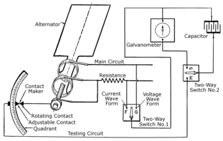
The history of the oscilloscope was fundamental to science because an oscilloscope is a device for viewing waveform oscillations, as of electrical voltage or current, in order to measure frequency and other wave characteristics. This was important in developing electromagnetic theory. The first recordings of waveforms were with a galvanometer coupled to a mechanical drawing system dating from the second decade of the 19th century. The modern day digital oscilloscope is a consequence of multiple generations of development of the oscillograph, cathode-ray tubes, analog oscilloscopes, and digital electronics.
A digital signal is a signal that represents data as a sequence of discrete values; at any given time it can only take on, at most, one of a finite number of values. This contrasts with an analog signal, which represents continuous values; at any given time it represents a real number within a continuous range of values.

An audio analyzer is a test and measurement instrument used to objectively quantify the audio performance of electronic and electro-acoustical devices. Audio quality metrics cover a wide variety of parameters, including level, gain, noise, harmonic and intermodulation distortion, frequency response, relative phase of signals, interchannel crosstalk, and more. In addition, many manufacturers have requirements for behavior and connectivity of audio devices that require specific tests and confirmations.
The following outline is provided as an overview of and topical guide to electronics:
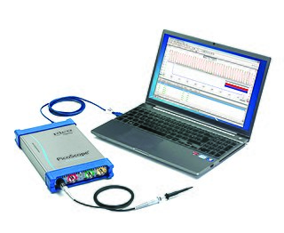
Pico Technology is a British manufacturer of high-precision PC-based oscilloscopes and automotive diagnostics equipment, founded in 1991. Their product range includes the PicoScope line of PC-based oscilloscopes, data loggers, automotive equipment, and most recently, handheld USB-based oscilloscopes. Since their inception in 1991, Pico Tech has been researching and developing PC-based oscilloscopes, when the market standard was analogue storage oscilloscopes. Pico Technology is one of two European scope manufacturers, and competes in the low to middle end of the instrumentation market.