Demonstration model of a moving iron ammeter. As the current through the coil increases, the plunger is drawn further into the coil and the pointer deflects to the right.
An ammeter (abbreviation of ampere meter) is an instrument used to measure the current in a circuit. Electric currents are measured in amperes (A), hence the name. For direct measurement, the ammeter is connected in series with the circuit in which the current is to be measured. An ammeter usually has low resistance so that it does not cause a significant voltage drop in the circuit being measured.
Instruments used to measure smaller currents, in the milliampere or microampere range, are designated as milliammeters or microammeters. Early ammeters were laboratory instruments that relied on the Earth's magnetic field for operation. By the late 19thcentury, improved instruments were designed which could be mounted in any position and allowed accurate measurements in electric power systems. It is generally represented by letter 'A' in a circuit.
Ammeter from the University of Dundee Physics Department
The relation between electric current, magnetic fields and physical forces was first noted by Hans Christian Ørsted in 1820, who observed a compass needle was deflected from pointing North when a current flowed in an adjacent wire. The tangent galvanometer was used to measure currents using this effect, where the restoring force returning the pointer to the zero position was provided by the Earth's magnetic field. This made these instruments usable only when aligned with the Earth's field. Sensitivity of the instrument was increased by using additional turns of wire to multiply the effect – the instruments were called "multipliers".[1]
The word rheoscope as a detector of electrical currents was coined by Sir Charles Wheatstone about 1840 but is no longer used to describe electrical instruments. The word makeup is similar to that of rheostat (also coined by Wheatstone) which was a device used to adjust the current in a circuit. Rheostat is a historical term for a variable resistance, though unlike rheoscope may still be encountered.[2][3]
Types
Some instruments are panel meters, meant to be mounted on some sort of control panel. Of these, the flat, horizontal or vertical type is often called an edgewise meter.
Moving-coil
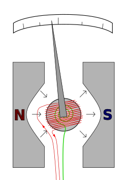
Wire carrying current to be measured. Spring providing restoring force This illustration is conceptual; in a practical meter, the iron core is stationary, and front and rear spiral springs carry current to the coil, which is supported on a rectangular bobbin. Furthermore, the poles of the permanent magnet are arcs of a circle.
The D'Arsonval galvanometer is a moving coil ammeter. It uses magneticdeflection, where current passing through a coil placed in the magnetic field of a permanent magnet causes the coil to move. The modern form of this instrument was developed by Edward Weston, and uses two spiral springs to provide the restoring force. The uniform air gap between the iron core and the permanent magnet poles make the deflection of the meter linearly proportional to current. These meters have linear scales. Basic meter movements can have full-scale deflection for currents from about 25microamperes to 10milliamperes.[4]
Because the magnetic field is polarised, the meter needle acts in opposite directions for each direction of current. A DCammeter is thus sensitive to which polarity it is connected in; most are marked with a positive terminal, but some have centre-zero mechanisms[a] and can display currents in either direction. A moving coil meter indicates the average (mean) of a varying current through it,[b] which is zero for AC. For this reason, moving-coil meters are only usable directly for DC, not AC.
This type of meter movement is extremely common for both ammeters and other meters derived from them, such as voltmeters and ohmmeters.
Moving magnet
Moving magnet ammeters operate on essentially the same principle as moving coil, except that the coil is mounted in the meter case, and a permanent magnet moves the needle. Moving magnet Ammeters are able to carry larger currents than moving coil instruments, often several tens of amperes, because the coil can be made of thicker wire and the current does not have to be carried by the hairsprings. Indeed, some Ammeters of this type do not have hairsprings at all, instead using a fixed permanent magnet to provide the restoring force.
Electrodynamic
An electrodynamic ammeter uses an electromagnet instead of the permanent magnet of the d'Arsonval movement. This instrument can respond to both alternating and direct current[4] and also indicates true RMS for AC. See wattmeter for an alternative use for this instrument.
Moving-iron
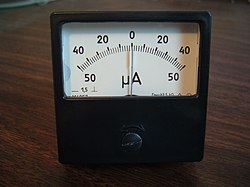
Face of an older moving iron ammeter with its characteristic non-linear scale. The moving iron ammeter symbol is in the lower-left corner of the meter face.
Moving iron ammeters use a piece of iron which moves when acted upon by the electromagnetic force of a fixed coil of wire. The moving-iron meter was invented by Austrian engineer Friedrich Drexler in 1884.[5] This type of meter responds to both direct and alternating currents (as opposed to the moving-coil ammeter, which works on direct current only). The iron element consists of a moving vane attached to a pointer, and a fixed vane, surrounded by a coil. As alternating or direct current flows through the coil and induces a magnetic field in both vanes, the vanes repel each other and the moving vane deflects against the restoring force provided by fine helical springs.[4] The deflection of a moving iron meter is proportional to the square of the current. Consequently, such meters would normally have a nonlinear scale, but the iron parts are usually modified in shape to make the scale fairly linear over most of its range. Moving iron instruments indicate the RMS value of any AC waveform applied. Moving iron ammeters are commonly used to measure current in industrial frequency AC circuits.
Hot-wire
A hot-wire ammeter
In a hot-wire ammeter, a current passes through a wire which expands as it heats. Although these instruments have slow response time and low accuracy, they were sometimes used in measuring radio-frequency current.[4] These also measure true RMS for an applied AC.
Digital
In much the same way as the analogue ammeter formed the basis for a wide variety of derived meters, including voltmeters, the basic mechanism for a digital meter is a digital voltmeter mechanism, and other types of meter are built around this.
Digital ammeter designs use a shunt resistor to produce a calibrated voltage proportional to the current flowing. This voltage is then measured by a digital voltmeter, through use of an analog-to-digital converter (ADC); the digital display is calibrated to display the current through the shunt. Such instruments are often calibrated to indicate the RMS value for a sine wave only, but many designs will indicate true RMS within limitations of the wave crest factor.
Integrating
An integrating current meter calibrated in ampere-hours or charge
There is also a range of devices referred to as integrating ammeters.[6][7] In these ammeters the current is summed over time, giving as a result the product of current and time; which is proportional to the electrical charge transferred with that current. These can be used for metering energy (the charge needs to be multiplied by the voltage to give energy) or for estimating the charge of a battery or capacitor.
Picoammeter
A picoammeter, or pico ammeter, measures very low electric current, usually from the picoampere range at the lower end to the milliampere range at the upper end. Picoammeters are used where the current being measured is below the limits of sensitivity of other devices, such as multimeters.
Most picoammeters use a "virtual short" technique and have several different measurement ranges that must be switched between to cover multiple decades of measurement. Other modern picoammeters use log compression and a "current sink" method that eliminates range switching and associated voltage spikes.[8] Special design and usage considerations must be observed in order to reduce leakage current which may swamp measurements such as special insulators and driven shields. Triaxial cable is often used for probe connections.
Application
Ammeters must be connected in series with the circuit to be measured. For relatively small currents (up to a few amperes), an ammeter may pass the whole of the circuit current. For larger direct currents, a shunt resistor carries most of the circuit current and a small, accurately-known fraction of the current passes through the meter movement. For alternating current circuits, a current transformer may be used to provide a convenient small current to drive an instrument, such as 1 or 5 amperes, while the primary current to be measured is much larger (up to thousands of amperes). The use of a shunt or current transformer also allows convenient location of the indicating meter without the need to run heavy circuit conductors up to the point of observation. In the case of alternating current, the use of a current transformer also isolates the meter from the high voltage of the primary circuit. A shunt provides no such isolation for a direct-current ammeter, but where high voltages are used it may be possible to place the ammeter in the "return" side of the circuit which may be at low potential with respect to earth.
Ammeters must not be connected directly across a voltage source since their internal resistance is very low and excess current would flow. Ammeters are designed for a low voltage drop across their terminals, much less than one volt; the extra circuit losses produced by the ammeter are called its "burden" on the measured circuit(I).
Ordinary Weston-type meter movements can measure only milliamperes at most, because the springs and practical coils can carry only limited currents. To measure larger currents, a resistor called a shunt is placed in parallel with the meter. The resistances of shunts is in the integer to fractional milliohm range. Nearly all of the current flows through the shunt, and only a small fraction flows through the meter. This allows the meter to measure large currents. Traditionally, the meter used with a shunt has a full-scale deflection (FSD) of 50 mV, so shunts are typically designed to produce a voltage drop of 50 mV when carrying their full rated current.
Ayrton shunt switching principle
To make a multi-range ammeter, a selector switch can be used to connect one of a number of shunts across the meter. It must be a make-before-break switch to avoid damaging current surges through the meter movement when switching ranges.
A better arrangement is the Ayrton shunt or universal shunt, invented by William E. Ayrton, which does not require a make-before-break switch. It also avoids any inaccuracy because of contact resistance. In the figure, assuming for example, a movement with a full-scale voltage of 50mV and desired current ranges of 10mA, 100mA, and 1A, the resistance values would be: R1 = 4.5ohms, R2 = 0.45ohm, R3 = 0.05ohm. And if the movement resistance is 1000ohms, for example, R1 must be adjusted to 4.525ohms.
Switched shunts are rarely used for currents above 10 amperes.
Zero-center ammeter
Zero-center ammeters are used for applications requiring current to be measured with both polarities, common in scientific and industrial equipment. Zero-center ammeters are also commonly placed in series with a battery. In this application, the charging of the battery deflects the needle to one side of the scale (commonly, the right side) and the discharging of the battery deflects the needle to the other side. A special type of zero-center ammeter for testing high currents in cars and trucks has a pivoted bar magnet that moves the pointer, and a fixed bar magnet to keep the pointer centered with no current. The magnetic field around the wire carrying current to be measured deflects the moving magnet.
Since the ammeter shunt has a very low resistance, mistakenly wiring the ammeter in parallel with a voltage source will cause a short circuit, at best blowing a fuse, possibly damaging the instrument and wiring, and exposing an observer to injury.
In AC circuits, a current transformer can be used to convert the large current in the main circuit into a smaller current more suited to a meter. Some designs of transformer are able to directly convert the magnetic field around a conductor into a small AC current, typically either 1 A or 5 A at full rated current, that can be easily read by a meter. In a similar way, accurate AC/DC non-contact ammeters have been constructed using Hall effect magnetic field sensors. A portable hand-held clamp-on ammeter is a common tool for maintenance of industrial and commercial electrical equipment, which is temporarily clipped over a wire to measure current. Some recent types have a parallel pair of magnetically soft probes that are placed on either side of the conductor.
In particle accelerators and synchrotron light sources, ammeters with extremely high sensitivity, known as picoammeters, are used to measure the tiny currents generated by photodiodes and other beam position monitors (BPMs). These instruments typically provide multiple low-noise input channels with femtoampere to microampere sensitivity, enabling real-time determination of the photon beam position and intensity. Such devices are crucial for beam stabilization and feedback systems in facilities like the Advanced Photon Source at Argonne National Laboratory, where custom picoammeters are employed to ensure precise orbit control and improved beamline performance.[9]
↑ The needle's resting position is in the centre of the scale and the restoring spring can act equally well in either direction.
↑ It shows an average provided that the current's frequency is faster than the meter can respond to.
References
↑ Geddes, L.A. (Feb–Mar 1996). "Looking back: How measuring electric current has improved through the ages". IEEE Potentials. 15: 40–42. doi:10.1109/MP.1996.481376. S2CID11392090.
1 2 3 4 Spitzer, Frank; Howarth, Barry (1972). Principles of Modern Instrumentation. New York, NY: Holt, Rinehart, and Winston. chapter11. ISBN0-03-080208-3.
This page is based on this Wikipedia article Text is available under the CC BY-SA 4.0 license; additional terms may apply. Images, videos and audio are available under their respective licenses.