Ohmmeter

Last updated
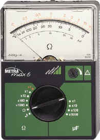
An analog ohmmeter Ohmmeter.jpg
An analog ohmmeter

An ohmmeter is an electrical instrument that measures electrical resistance (the opposition offered by a circuit or component to the flow of electric current). Multimeters also function as ohmmeters when in resistance-measuring mode. An ohmmeter applies current to the circuit or component whose resistance is to be measured. It then measures the resulting voltage and calculates the resistance using Ohm’s law .

Contents

An ohmmeter should not be connected to a circuit or component that is carrying a current or is connected to a power source. Power should be disconnected before connecting the ohmmeter. Ohmmeters can be either connected in series or parallel based on requirements (whether resistance being measured is part of circuit or is a shunt resistance).

Micro-ohmmeters (microhmmeter or micro ohmmeter) make measurements of low resistance. Megohmmeters (also a trademarked device Megger) measure large values of resistance. The unit of measurement for resistance is the ohm (Ω).

Design evolution

The first ohmmeters were based on a type of meter movement known as a 'ratiometer'. [1] [2] These were similar to the galvanometer type movement encountered in later instruments, but instead of hairsprings to supply a restoring force they used conducting 'ligaments'. These provided no net rotational force to the movement. Also, the movement was wound with two coils. One was connected via a series resistor to the battery supply. The second was connected to the same battery supply via a second resistor and the resistor under test. The indication on the meter was proportional to the ratio of the currents through the two coils. This ratio was determined by the magnitude of the resistor under test. The advantages of this arrangement were twofold. First, the indication of the resistance was completely independent of the battery voltage (as long as it actually produced some voltage) and no zero adjustment was required. Second, although the resistance scale was non linear, the scale remained correct over the full deflection range. By interchanging the two coils a second range was provided. This scale was reversed compared to the first. A feature of this type of instrument was that it would continue to indicate a random resistance value once the test leads were disconnected (the action of which disconnected the battery from the movement). Ohmmeters of this type only ever measured resistance as they could not easily be incorporated into a multimeter design. Insulation testers that relied on a hand cranked generator operated on the same principle. This ensured that the indication was wholly independent of the voltage actually produced.

Subsequent designs of ohmmeter provided a small battery to apply a voltage to a resistance via a galvanometer to measure the current through the resistance (battery, galvanometer and resistance all connected in series). The scale of the galvanometer was marked in ohms, because the fixed voltage from the battery assured that as resistance is increased, the current through the meter (and hence deflection) would decrease. Ohmmeters form circuits by themselves, therefore they cannot be used within an assembled circuit. This design is much simpler and cheaper than the former design, and was simple to integrate into a multimeter design and consequently was by far the most common form of analogue ohmmeter. This type of ohmmeter suffers from two inherent disadvantages. First, the meter needs to be zeroed by shorting the measurement points together and performing an adjustment for zero ohms indication prior to each measurement. This is because as the battery voltage decreases with age, the series resistance in the meter needs to be reduced to maintain the zero indication at full deflection. Second, and consequent on the first, the actual deflection for any given resistor under test changes as the internal resistance is altered. It remains correct at the centre of the scale only, which is why such ohmmeter designs always quote the accuracy "at centre scale only".

A more accurate type of ohmmeter has an electronic circuit that passes a constant current (I) through the resistance, and another circuit that measures the voltage (V) across the resistance. These measurements are then digitized with an analog digital converter (adc) after which a microcontroller or microprocessor make the division of the current and voltage according to Ohm's law and then decode these to a display to offer the user a reading of the resistance value they're measuring at that instant. Since these type of meters already measure current, voltage and resistance all at once, these type of circuits are often used in digital multimeters.

Precision ohmmeters

For high-precision measurements of very small resistances, the above types of meter are inadequate. This is partly because the change in deflection itself is small when the resistance measured is too small in proportion to the intrinsic resistance of the ohmmeter (which can be dealt with through current division), but mostly because the meter's reading is the sum of the resistance of the measuring leads, the contact resistances and the resistance being measured. To reduce this effect, a precision ohmmeter has four terminals, called Kelvin contacts. Two terminals carry the current from and to the meter, while the other two allow the meter to measure the voltage across the resistor. In this arrangement, the power source is connected in series with the resistance to be measured through the external pair of terminals, while the second pair connects in parallel with the galvanometer which measures the voltage drop. With this type of meter, any voltage drop due to the resistance of the first pair of leads and their contact resistances is ignored by the meter. This four terminal measurement technique is called Kelvin sensing, after William Thomson, Lord Kelvin, who invented the Kelvin bridge in 1861 to measure very low resistances. The Four-terminal sensing method can also be utilized to conduct accurate measurements of low resistances.

Related Research Articles

<span class="mw-page-title-main">Ammeter</span> Device that measures electric current

An ammeter is an instrument used to measure the current in a circuit. Electric currents are measured in amperes (A), hence the name. For direct measurement, the ammeter is connected in series with the circuit in which the current is to be measured. An ammeter usually has low resistance so that it does not cause a significant voltage drop in the circuit being measured.

<span class="mw-page-title-main">Resistor</span> Passive electrical component providing electrical resistance

A resistor is a passive two-terminal electrical component that implements electrical resistance as a circuit element. In electronic circuits, resistors are used to reduce current flow, adjust signal levels, to divide voltages, bias active elements, and terminate transmission lines, among other uses. High-power resistors that can dissipate many watts of electrical power as heat may be used as part of motor controls, in power distribution systems, or as test loads for generators. Fixed resistors have resistances that only change slightly with temperature, time or operating voltage. Variable resistors can be used to adjust circuit elements, or as sensing devices for heat, light, humidity, force, or chemical activity.

<span class="mw-page-title-main">Voltmeter</span> Instrument used for measuring voltage

A voltmeter is an instrument used for measuring electric potential difference between two points in an electric circuit. It is connected in parallel. It usually has a high resistance so that it takes negligible current from the circuit.

<span class="mw-page-title-main">Wheatstone bridge</span> Resistometer

A Wheatstone bridge is an electrical circuit used to measure an unknown electrical resistance by balancing two legs of a bridge circuit, one leg of which includes the unknown component. The primary benefit of the circuit is its ability to provide extremely accurate measurements. Its operation is similar to the original potentiometer.

<span class="mw-page-title-main">Galvanometer</span> Instrument to measure electric current

A galvanometer is an electromechanical measuring instrument for electric current. Early galvanometers were uncalibrated, but improved versions, called ammeters, were calibrated and could measure the flow of current more precisely.

<span class="mw-page-title-main">Multimeter</span> Electronic measuring instrument that combines several measurement functions in one unit

A multimeter is a measuring instrument that can measure multiple electrical properties. A typical multimeter can measure voltage, resistance, and current, in which case can be used as a voltmeter, ammeter, and ohmmeter. Some feature the measurement of additional properties such as temperature and capacitance.

<span class="mw-page-title-main">Electrical resistance and conductance</span> Opposition to the passage of an electric current

The electrical resistance of an object is a measure of its opposition to the flow of electric current. Its reciprocal quantity is electrical conductance, measuring the ease with which an electric current passes. Electrical resistance shares some conceptual parallels with mechanical friction. The SI unit of electrical resistance is the ohm, while electrical conductance is measured in siemens (S).

A shunt is a device that is designed to provide a low-resistance path for an electrical current in a circuit. It is typically used to divert current away from a system or component in order to prevent overcurrent. Electrical shunts are commonly used in a variety of applications including power distribution systems, electrical measurement systems, automotive and marine applications.

<span class="mw-page-title-main">Wattmeter</span> Device that measures electric power

The wattmeter is an instrument for measuring the electric active power in watts of any given circuit. Electromagnetic wattmeters are used for measurement of utility frequency and audio frequency power; other types are required for radio frequency measurements.

load cell converts a force such as tension, compression, pressure, or torque into a signal that can be measured and standardized. It is a force transducer. As the force applied to the load cell increases, the signal changes proportionally. The most common types of load cells are pneumatic, hydraulic, and strain gauge types for industrial applications. Typical non-electronic bathroom scales are a widespread example of a mechanical displacement indicator where the applied weight (force) is indicated by measuring the deflection of springs supporting the load platform, technically a "load cell".

<span class="mw-page-title-main">Avometer</span> Line of multimeters

AVOmeter is a British trademark for a line of multimeters and electrical measuring instruments; the brand is now owned by the Megger Group Limited. The first Avometer was made by the Automatic Coil Winder and Electrical Equipment Co. in 1923, and measured direct voltage, direct current and resistance. Possibly the best known multimeter of the range was the Model 8, which was produced in various versions from May 1951 until 2008; the last version was the Mark 7.

<span class="mw-page-title-main">Current clamp</span> Tool for measuring electrical current

In electrical and electronic engineering, a current clamp, also known as current probe, is an electrical device with jaws which open to allow clamping around an electrical conductor. This allows measurement of the current in a conductor without the need to make physical contact with it, or to disconnect it for insertion through the probe.

<span class="mw-page-title-main">Capacitance meter</span> Type of electronic test equipment

A capacitance meter is a piece of electronic test equipment used to measure capacitance, mainly of discrete capacitors. Depending on the sophistication of the meter, it may display the capacitance only, or it may also measure a number of other parameters such as leakage, equivalent series resistance (ESR), and inductance. For most purposes and in most cases the capacitor must be disconnected from circuit; ESR can usually be measured in circuit.

<span class="mw-page-title-main">Test probe</span>

A test probe is a physical device used to connect electronic test equipment to a device under test (DUT). Test probes range from very simple, robust devices to complex probes that are sophisticated, expensive, and fragile. Specific types include test prods, oscilloscope probes and current probes. A test probe is often supplied as a test lead, which includes the probe, cable and terminating connector.

<span class="mw-page-title-main">Four-terminal sensing</span> Method of measuring electrical impedance

In electrical engineering, four-terminal sensing, 4-wire sensing, or 4-point probes method is an electrical impedance measuring technique that uses separate pairs of current-carrying and voltage-sensing electrodes to make more accurate measurements than the simpler and more usual two-terminal (2T) sensing. Four-terminal sensing is used in some ohmmeters and impedance analyzers, and in wiring for strain gauges and resistance thermometers. Four-point probes are also used to measure sheet resistance of thin films.

A Kelvin bridge, also called a Kelvin double bridge and in some countries a Thomson bridge, is a measuring instrument used to measure unknown electrical resistors below 1 ohm. It is specifically designed to measure resistors that are constructed as four terminal resistors.

A potentiometer is an instrument for measuring voltage or 'potential difference' by comparison of an unknown voltage with a known reference voltage. If a sensitive indicating instrument is used, very little current is drawn from the source of the unknown voltage. Since the reference voltage can be produced from an accurately calibrated voltage divider, a potentiometer can provide high precision in measurement. The method was described by Johann Christian Poggendorff around 1841 and became a standard laboratory measuring technique.

<span class="mw-page-title-main">Megohmmeter</span>

A Megohmmeter or insulation resistance tester, also colloquially known as megger, is a special type of ohmmeter used to measure the electrical resistance of insulators. Insulating components, for example cable jackets, must be tested for their insulation strength at the time of commissioning and as part of maintenance of high voltage electrical equipment and installations.

<span class="mw-page-title-main">Megger Group Limited</span>

Megger Group Limited is a British manufacturing company that manufactures electronic test equipment and measuring instruments for electrical power applications.

<span class="mw-page-title-main">ESR meter</span> Tool for measuring equivalent series resistance of capacitors

An ESR meter is a two-terminal electronic measuring instrument designed and used primarily to measure the equivalent series resistance (ESR) of real capacitors; usually without the need to disconnect the capacitor from the circuit it is connected to. Other types of meters used for routine servicing, including normal capacitance meters, cannot be used to measure a capacitor's ESR, although combined meters are available that measure both ESR and out-of-circuit capacitance. A standard (DC) milliohmmeter or multimeter cannot be used to measure ESR, because a steady direct current cannot be passed through the capacitor. Most ESR meters can also be used to measure non-inductive low-value resistances, whether or not associated with a capacitor; this leads to several additional applications described below.

References

https://www.codrey.com/electrical/ohmmeter-working-and-types/