In electronics, the figures of merit of an amplifier are numerical measures that characterize its properties and performance. Figures of merit can be given as a list of specifications that include properties such as gain, bandwidth, noise and linearity, among others listed in this article. Figures of merit are important for determining the suitability of a particular amplifier for an intended use.

An amplifier, electronic amplifier or (informally) amp is an electronic device that can increase the power of a signal. It is a two-port electronic circuit that uses electric power from a power supply to increase the amplitude of a signal applied to its input terminals, producing a proportionally greater amplitude signal at its output. The amount of amplification provided by an amplifier is measured by its gain: the ratio of output voltage, current, or power to input. An amplifier is a circuit that has a power gain greater than one.

An operational amplifier is a DC-coupled high-gain electronic voltage amplifier with a differential input and, usually, a single-ended output. In this configuration, an op amp produces an output potential that is typically 100,000 times larger than the potential difference between its input terminals. Operational amplifiers had their origins in analog computers, where they were used to perform mathematical operations in linear, non-linear, and frequency-dependent circuits.
A low-noise amplifier (LNA) is an electronic amplifier that amplifies a very low-power signal without significantly degrading its signal-to-noise ratio. An amplifier will increase the power of both the signal and the noise present at its input, but the amplifier will also introduce some additional noise. LNAs are designed to minimize that additional noise. Designers can minimize additional noise by choosing low-noise components, operating points, and circuit topologies. Minimizing additional noise must balance with other design goals such as power gain and impedance matching.
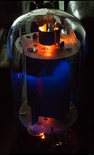
A valve amplifier or tube amplifier is a type of electronic amplifier that uses vacuum tubes to increase the amplitude or power of a signal. Low to medium power valve amplifiers for frequencies below the microwaves were largely replaced by solid state amplifiers in the 1960s and 1970s. Valve amplifiers can be used for applications such as guitar amplifiers, satellite transponders such as DirecTV and GPS, high quality stereo amplifiers, military applications and very high power radio and UHF television transmitters.

A voltage regulator is a system designed to automatically maintain a constant voltage. A voltage regulator may use a simple feed-forward design or may include negative feedback. It may use an electromechanical mechanism, or electronic components. Depending on the design, it may be used to regulate one or more AC or DC voltages.
Scattering parameters or S-parameters describe the electrical behavior of linear electrical networks when undergoing various steady state stimuli by electrical signals.

A class-D amplifier or switching amplifier is an electronic amplifier in which the amplifying devices operate as electronic switches, and not as linear gain devices as in other amplifiers. They operate by rapidly switching back and forth between the supply rails, being fed by a modulator using pulse width, pulse density, or related techniques to encode the audio input into a pulse train. The audio escapes through a simple low-pass filter into the loudspeaker. The high-frequency pulses are blocked. Since the pairs of output transistors are never conducting at the same time, there is no other path for current flow apart from the low-pass filter/loudspeaker. For this reason, efficiency can exceed 90%.
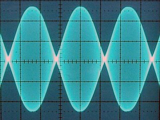
A linear amplifier is an electronic circuit whose output is proportional to its input, but capable of delivering more power into a load. The term usually refers to a type of radio-frequency (RF) power amplifier, some of which have output power measured in kilowatts, and are used in amateur radio. Other types of linear amplifier are used in audio and laboratory equipment. Linearity refers to the ability of the amplifier to produce signals that are accurate copies of the input. A linear amplifier responds to different frequency components independently, and tends not to generate harmonic distortion or intermodulation distortion. No amplifier can provide perfect linearity however, because the amplifying devices—transistors or vacuum tubes—follow nonlinear power laws and rely on circuitry techniques to reduce those effects. There are a number of amplifier classes providing various trade-offs between implementation cost, efficiency, and signal accuracy.
The cascode is a two-stage amplifier that consists of a common-emitter stage feeding into a common-base stage.

A network analyzer is an instrument that measures the network parameters of electrical networks. Today, network analyzers commonly measure s–parameters because reflection and transmission of electrical networks are easy to measure at high frequencies, but there are other network parameter sets such as y-parameters, z-parameters, and h-parameters. Network analyzers are often used to characterize two-port networks such as amplifiers and filters, but they can be used on networks with an arbitrary number of ports.

A test probe is a physical device used to connect electronic test equipment to a device under test (DUT). Test probes range from very simple, robust devices to complex probes that are sophisticated, expensive, and fragile. Specific types include test prods, oscilloscope probes and current probes. A test probe is often supplied as a test lead, which includes the probe, cable and terminating connector.
An active load or dynamic load is a component or a circuit that functions as a current-stable nonlinear resistor.
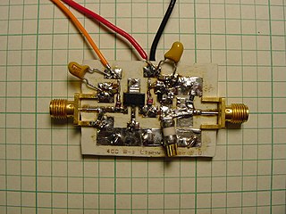
A radio frequency power amplifier is a type of electronic amplifier that converts a low-power radio-frequency signal into a higher power signal. Typically, RF power amplifiers drive the antenna of a transmitter. Design goals often include gain, power output, bandwidth, power efficiency, linearity, input and output impedance matching, and heat dissipation.
In the field of electronics, a technique where part of the output of a system is used at startup can be described as bootstrapping.
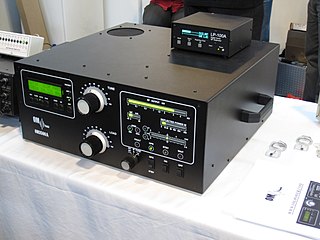
A valve RF amplifier or tube amplifier (U.S.) is a device for electrically amplifying the power of an electrical radio frequency signal.
Technical specifications and detailed information on the valve audio amplifier, including its development history.

In graphical analysis of nonlinear electronic circuits, a load line is a line drawn on the characteristic curve, a graph of the current vs. the voltage in a nonlinear device like a diode or transistor. It represents the constraint put on the voltage and current in the nonlinear device by the external circuit. The load line, usually a straight line, represents the response of the linear part of the circuit, connected to the nonlinear device in question. The points where the characteristic curve and the load line intersect are the possible operating point(s) of the circuit; at these points the current and voltage parameters of both parts of the circuit match.
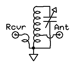
A preselector is a name for an electronic device that connects between a radio antenna and a radio receiver. The preselector is a band-pass filter that blocks troublesome out-of-tune frequencies from passing through from the antenna into the radio receiver that otherwise would be directly connected to the antenna.

Tube sound is the characteristic sound associated with a vacuum tube amplifier, a vacuum tube-based audio amplifier. At first, the concept of tube sound did not exist, because practically all electronic amplification of audio signals was done with vacuum tubes and other comparable methods were not known or used. After introduction of solid state amplifiers, tube sound appeared as the logical complement of transistor sound, which had some negative connotations due to crossover distortion in early transistor amplifiers. However, solid state amplifiers have been developed to be flawless and the sound is later regarded neutral compared to tube amplifiers. Thus the tube sound now means 'euphonic distortion.' The audible significance of tube amplification on audio signals is a subject of continuing debate among audio enthusiasts.