Electronic test equipment

Last updated
Tektronix 7854 oscilloscope with curve tracer and time-domain reflectometer plug-ins. Lower module is a mainframe of the series Tektronix TM500 and has a digital voltmeter, a digital counter, an old WWVB frequency standard receiver with phase comparator, and function generator. Oscilloscope Tektronix 7854 on Tektronix lab cart with four smaller electronic measurement and test devices underneath.jpg
Tektronix 7854 oscilloscope with curve tracer and time-domain reflectometer plug-ins. Lower module is a mainframe of the series Tektronix TM500 and has a digital voltmeter, a digital counter, an old WWVB frequency standard receiver with phase comparator, and function generator.

Electronic test equipment is used to create signals and capture responses from electronic devices under test (DUTs). In this way, the proper operation of the DUT can be proven or faults in the device can be traced. Use of electronic test equipment is essential to any serious work on electronics systems.

Contents

Practical electronics engineering and assembly requires the use of many different kinds of electronic test equipment ranging from the very simple and inexpensive (such as a test light consisting of just a light bulb and a test lead) to extremely complex and sophisticated such as automatic test equipment (ATE). ATE often includes many of these instruments in real and simulated forms.

Generally, more advanced test gear is necessary when developing circuits and systems than is needed when doing production testing or when troubleshooting existing production units in the field.[ citation needed ]

Types of test equipment

Basic equipment

Keysight commercial digital voltmeter checking a prototype Voltmeter.jpg
Keysight commercial digital voltmeter checking a prototype

The following items are used for basic measurement of voltages, currents, and components in the circuit under test.

The following are used for stimulus of the circuit under test:

Voltcraft M-3850 portable multimeter Digital Multimeter Aka.jpg
Voltcraft M-3850 portable multimeter

The following analyze the response of the circuit under test:

And connecting it all together:

Advanced or less commonly used equipment

Meters

Probes

A multimeter with a built in clamp facility. Pushing the large button at the bottom opens the lower jaw of the clamp, allowing the clamp to be placed around a conductor (wire). Depending on sensor, some can measure both AC and DC current. Tongtester.jpg
A multimeter with a built in clamp facility. Pushing the large button at the bottom opens the lower jaw of the clamp, allowing the clamp to be placed around a conductor (wire). Depending on sensor, some can measure both AC and DC current.

Analyzers

Signal-generating devices

Leader Instruments LSG-15 signal generator. Leader LSG-15 signal generator.jpg
Leader Instruments LSG-15 signal generator.
Cable tester Cable tester.jpg
Cable tester

Miscellaneous devices

Platforms

Keithley Instruments Series 4200 CVU Keithley-model4200-CVU.jpg
Keithley Instruments Series 4200 CVU

Several modular electronic instrumentation platforms are currently in common use for configuring automated electronic test and measurement systems. These systems are widely employed for incoming inspection, quality assurance, and production testing of electronic devices and subassemblies. Industry-standard communication interfaces link signal sources with measurement instruments in “rack-and-stack” or chassis-/mainframe-based systems, often under the control of a custom software application running on an external PC.

GPIB/IEEE-488

The General Purpose Interface Bus (GPIB) is an IEEE-488 (a standard created by the Institute of Electrical and Electronics Engineers) standard parallel interface used for attaching sensors and programmable instruments to a computer. GPIB is a digital 8-bit parallel communications interface capable of achieving data transfers of more than 8 Mbytes/s. It allows daisy-chaining up to 14 instruments to a system controller using a 24-pin connector. It is one of the most common I/O interfaces present in instruments and is designed specifically for instrument control applications. The IEEE-488 specifications standardized this bus and defined its electrical, mechanical, and functional specifications, while also defining its basic software communication rules. GPIB works best for applications in industrial settings that require a rugged connection for instrument control.

The original GPIB standard was developed in the late 1960s by Hewlett-Packard to connect and control the programmable instruments the company manufactured. The introduction of digital controllers and programmable test equipment created a need for a standard, high-speed interface for communication between instruments and controllers from various vendors. In 1975, the IEEE published ANSI/IEEE Standard 488–1975, IEEE Standard Digital Interface for Programmable Instrumentation, which contained the electrical, mechanical, and functional specifications of an interfacing system. This standard was subsequently revised in 1978 (IEEE-488.1) and 1990 (IEEE-488.2). The IEEE 488.2 specification includes the Standard Commands for Programmable Instrumentation (SCPI), which define specific commands that each instrument class must obey. SCPI ensures compatibility and configurability among these instruments.

The IEEE-488 bus has long been popular because it is simple to use and takes advantage of a large selection of programmable instruments and stimuli. Large systems, however, have the following limitations:

LAN eXtensions for Instrumentation

The LXI (LXI) Standard defines the communication protocols for instrumentation and data acquisition systems using Ethernet. These systems are based on small, modular instruments, using low-cost, open-standard LAN (Ethernet). LXI-compliant instruments offer the size and integration advantages of modular instruments without the cost and form factor constraints of card-cage architectures. Through the use of Ethernet communications, the LXI Standard allows for flexible packaging, high-speed I/O, and standardized use of LAN connectivity in a broad range of commercial, industrial, aerospace, and military applications. Every LXI-compliant instrument includes an Interchangeable Virtual Instrument (IVI) driver to simplify communication with non-LXI instruments, so LXI-compliant devices can communicate with devices that are not themselves LXI compliant (i.e., instruments that employ GPIB, VXI, PXI, etc.). This simplifies building and operating hybrid configurations of instruments.

LXI instruments sometimes employ scripting using embedded test script processors for configuring test and measurement applications. Script-based instruments provide architectural flexibility, improved performance, and lower cost for many applications. Scripting enhances the benefits of LXI instruments, and LXI offers features that both enable and enhance scripting. Although the current LXI standards for instrumentation do not require that instruments be programmable or implement scripting, several features in the LXI specification anticipate programmable instruments and provide useful functionality that enhances scripting's capabilities on LXI-compliant instruments. [3]

VME eXtensions for Instrumentation

VME eXtensions for Instrumentation (VXI) are an electrical and mechanical standard used mainly with automatic test equipment (ATE). VXI allows equipment from different vendors to work together in a common control and packaging environment. VPX (a.k.a. VITA 46) is an ANSI standard based on the VMEbus with support for switched fabric using a high speed connector. VXI combines VMEbus specifications with features from the general-purpose interface bus (GPIB) to meet the needs of instrumentation applications. Other technologies for VME, VPX and VXI controllers and processors may also be available.

Selecting VME, VPX and VXI bus interfaces and adapters requires an analysis of available technologies. The original VME bus (VMEbus) uses Eurocards, rugged circuit boards that provide a 96-pin plug instead of an edge connector for durability. VME64 is an expanded version of the VMEbus that provides 64-bit data transfers and addressing. VME64 features include asynchronous data transfers, an addressing range between 16 and 40 bits, data path widths between 8 and 64 bits, and a bandwidth of 80 Mbit/s. VME64 extended (VME64x) is an improved version of the original VMEbus that features a 160-pin connector family, 3.3 V power supply pins, bandwidths up to 160 Mbit/s, injector/ejector locking handles, and hot swap capability. VME160 transfers data at 160 Mbit/s. VME320 transfers data at a rate of 320 Mbit/s. VXI combines VMEbus specifications with features from the general-purpose interface bus (GPIB) to meet the needs of instrumentation applications. VME, VPX and VXI bus interfaces and adapters for VPX applications are also available. [4]

PCI eXtensions for Instrumentation

PCI eXtensions for Instrumentation, (PXI), is a peripheral bus specialized for data acquisition and real-time control systems. Introduced in 1997, PXI uses the CompactPCI 3U and 6U form factors and adds trigger lines, a local bus, and other functions suited for measurement applications. PXI hardware and software specifications are developed and maintained by the PXI Systems Alliance. [5] More than 50 manufacturers around the world produce PXI hardware. [6]

Universal Serial Bus

The Universal Serial Bus (USB) connects peripheral devices, such as keyboards and mice, to PCs. The USB is a Plug and Play bus that can handle up to 127 devices on one port, and has a theoretical maximum throughput of 480 Mbit/s (high-speed USB defined by the USB 2.0 specification). Because USB ports are standard features of PCs, they are a natural evolution of conventional serial port technology. However, it is not widely used in building industrial test and measurement systems for several reasons (e.g., USB cables are rarely industrial grade, are noise sensitive, are not positively attached and so are rather easily detachable, and the maximum distance between the controller and device is limited to a few meters). Like some other connections, USB is primarily used for applications in a laboratory setting that do not require a rugged bus connection.

RS-232

RS-232 is a specification for serial communication that is popular in analytical and scientific instruments, as well for controlling peripherals such as printers. Unlike GPIB, with the RS-232 interface, it is possible to connect and control only one device at a time. RS-232 is also a relatively slow interface with typical data rates of less than 20 kB/s. RS-232 is best suited for laboratory applications compatible with a slower, less rugged connection.

Test script processors and a channel expansion bus

One of the most recently developed test system platforms employs instrumentation equipped with onboard test script processors combined with a high-speed bus. In this approach, one “master” instrument runs a test script (a small program) that controls the operation of the various “slave” instruments in the test system, to which it is linked via a high-speed LAN-based trigger synchronization and inter-unit communication bus. Scripting is writing programs in a scripting language to coordinate a sequence of actions.

This approach is optimized for small message transfers that are characteristic of test and measurement applications. With very little network overhead and a 100 Mbit/s data rate, it is significantly faster than GPIB and 100BaseT Ethernet in real applications.

The advantage of this platform is that all connected instruments behave as one tightly integrated multi-channel system, so users can scale their test system to fit their required channel counts cost-effectively. A system configured on this type of platform can stand alone as a complete measurement and automation solution, with the master unit controlling sourcing, measuring, pass/fail decisions, test sequence flow control, binning, and the component handler or prober. Support for dedicated trigger lines means that synchronous operations between multiple instruments equipped with onboard Test Script Processors that are linked by this high-speed bus can be achieved without the need for additional trigger connections. [7]

Test equipment switching

The addition of a high-speed switching system to a test system's configuration allows for faster, more cost-effective testing of multiple devices, and is designed to reduce both test errors and costs. Designing a test system's switching configuration requires an understanding of the signals to be switched and the tests to be performed, as well as the switching hardware form factors available.

See also

Related Research Articles

<span class="mw-page-title-main">Eurocard (printed circuit board)</span> Standard for PCBs which may be interconnected in a rack mounted chassis

Eurocard is an IEEE standard format for printed circuit board (PCB) cards that can be plugged together into a standard chassis which, in turn, can be mounted in a 19-inch rack. The chassis consists of a series of slotted card guides on the top and bottom, into which the cards are slid so they stand on end, like books on a shelf. At the spine of each card is one or more connectors which plug into mating connectors on a backplane that closes the rear of the chassis.

<span class="mw-page-title-main">VMEbus</span> Computer bus standard physically based on Eurocard sizes

VMEbus is a computer bus standard, originally developed for the Motorola 68000 line of CPUs, but later widely used for many applications and standardized by the IEC as ANSI/IEEE 1014-1987. It is physically based on Eurocard sizes, mechanicals and connectors, but uses its own signalling system, which Eurocard does not define. It was first developed in 1981 and continues to see widespread use today.

Futurebus, or IEEE 896, is a computer bus standard, intended to replace all local bus connections in a computer, including the CPU, memory, plug-in cards and even, to some extent, LAN links between machines. The effort started in 1979 and didn't complete until 1987, and then immediately went into a redesign that lasted until 1994. By this point, implementation of a chip-set based on the standard lacked industry leadership. It has seen little real-world use, although custom implementations continue to be designed and used throughout industry.

<span class="mw-page-title-main">Data acquisition</span> Process of sampling signals from sensors and converting into digital data

Data acquisition is the process of sampling signals that measure real-world physical conditions and converting the resulting samples into digital numeric values that can be manipulated by a computer. Data acquisition systems, abbreviated by the acronyms DAS,DAQ, or DAU, typically convert analog waveforms into digital values for processing. The components of data acquisition systems include:

<span class="mw-page-title-main">IEEE-488</span> General Purpose Interface Bus (GPIB) specification

IEEE 488 is a short-range digital communications 8-bit parallel multi-master interface bus specification developed by Hewlett-Packard as HP-IB. It subsequently became the subject of several standards, and is generically known as GPIB.

LAN eXtensions for Instrumentation (LXI) is a standard developed by the LXI Consortium, a consortium that maintains the LXI specification and promotes the LXI Standard. The LXI standard defines the communication protocols for instrumentation and data acquisition systems using Ethernet. Ethernet is a ubiquitous communication standard providing a versatile interface, the LXI standard describes how to use the Ethernet standards for test and measurement applications in a way that promotes simple interoperability between instruments. The LXI Consortium ensures LXI compliant instrumentation developed by various vendors works together with no communication or setup issues. The LXI Consortium ensures that the LXI standard complements other test and measurement control systems, such as GPIB and PXI systems.

<span class="mw-page-title-main">CompactPCI</span> Computer bus interconnect for industrial computers

CompactPCI is a computer bus interconnect for industrial computers, combining a Eurocard-type connector and PCI signaling and protocols. Boards are standardized to 3U or 6U sizes, and are typically interconnected via a passive backplane. The connector pin assignments are standardized by the PICMG US and PICMG Europe organizations. The connectors and the electrical rules allow for eight boards in a PCI segment. Multiple bus segments are allowed with bridges.

<span class="mw-page-title-main">VME eXtensions for Instrumentation</span>

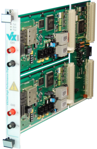
VME eXtensions for instrumentation bus refers to standards for automated test based upon VMEbus. VXI defines additional bus lines for timing and triggering as well as mechanical requirements and standard protocols for configuration, message-based communication, multi-chassis extension, and other features. In 2004, the 2eVME extension was added to the VXI bus specification, giving it a maximum data rate of 160 MB/s.

<span class="mw-page-title-main">Automatic test equipment</span> Apparatus used in hardware testing that carries out a series of tests automatically

Automatic test equipment or automated test equipment (ATE) is any apparatus that performs tests on a device, known as the device under test (DUT), equipment under test (EUT) or unit under test (UUT), using automation to quickly perform measurements and evaluate the test results. An ATE can be a simple computer-controlled digital multimeter, or a complicated system containing dozens of complex test instruments capable of automatically testing and diagnosing faults in sophisticated electronic packaged parts or on wafer testing, including system on chips and integrated circuits.

<span class="mw-page-title-main">PCI eXtensions for Instrumentation</span>

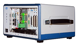
PCI eXtensions for Instrumentation (PXI) is one of several modular electronic instrumentation platforms in current use. These platforms are used as a basis for building electronic test equipment, automation systems, and modular laboratory instruments. PXI is based on industry-standard computer buses and permits flexibility in building equipment. Often, modules are fitted with custom software to manage the system.

Instrument control consists of connecting a desktop instrument to a computer and taking measurements.

<span class="mw-page-title-main">System on module</span> Board-level circuit that integrates a system function in a single module

A system on a module (SoM) is a board-level circuit that integrates a system function in a single module. It may integrate digital and analog functions on a single board. A typical application is in the area of embedded systems. Unlike a single-board computer, a SoM serves a special function like a system on a chip (SoC). The devices integrated in the SoM typically requires a high level of interconnection for reasons such as speed, timing, bus width etc.. There are benefits in building a SoM, as for SoC; one notable result is to reduce the cost of the base board or the main PCB. Two other major advantages of SoMs are design-reuse and that they can be integrated into many embedded computer applications.

<span class="mw-page-title-main">VPX</span> Standards for connecting components of a computer

VPX, also known as VITA 46, refers to a set of standards for connecting components of a computer, commonly used by defense contractors. Some are ANSI standards such as ANSI/VITA 46.0–2019. VPX provides VMEbus-based systems with support for switched fabrics over a new high speed connector. Defined by the VMEbus International Trade Association (VITA) working group starting in 2003, it was first demonstrated in 2004, and became an ANSI standard in 2007.

<span class="mw-page-title-main">Standard Commands for Programmable Instruments</span>

The Standard Commands for Programmable Instruments defines a standard for syntax and commands to use in controlling programmable test and measurement devices, such as automatic test equipment and electronic test equipment.

M-Modules are a mezzanine standard mainly used in industrial computers. Being mezzanines, they are always plugged on a carrier printed circuit board (PCB) that supports this format. The modules communicate with their carrier over a dedicated bus, and can have all kinds of special functions.

An instrument driver, in the context of test and measurement (T&M) application development, is a set of software routines that simplifies remote instrument control. Instrument drivers are specified by the IVI Foundation and define an I/O abstraction layer using the virtual instrument software architecture (VISA). The VISA hardware abstraction layer provides an interface-independent communication channel to T&M instruments. Furthermore, the instrument drivers encapsulate the Standard Commands for Programmable Instruments (SCPI) commands, which are an ASCII-based set of commands for reading and writing instrument settings and measurement data. This standard allows an abstract way of using various programming languages to program remote-control applications instead of using SCPI commands. An instrument driver usually has a well-defined API.

<span class="mw-page-title-main">Mass interconnect</span>

Mass interconnect systems act as the connector interface between test instruments and devices/units under test (D/UUT) and are most often used in defense, aerospace, automotive, manufacturing, and other applications. By mating a receiver on the tester side with an interchangeable test adapter (ITA) on the UUT, a mass interconnect enables the entire system to mate together at one time. Mass interconnect systems are available in multiple sizes and configurations to accommodate virtually any testing requirement.

<span class="mw-page-title-main">Elma Electronic</span>

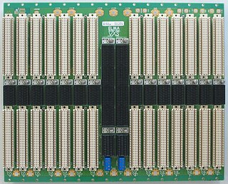
Elma Electronic is a publicly traded Swiss electronics company founded in 1960 and based in Wetzikon, Switzerland. The company has 5 product divisions: Systems Platforms, Backplanes, Enclosures & Components, Rotary Switches, and Cabinet Enclosures. The largest segment is systems packaging serving the military, aerospace, homeland security, medical and industrial markets. The Elma Bustronic division develops backplanes, including VME320, which was the world's fastest VME backplane in 1997. Elma Bustronic also develops backplanes in OpenVPX, VMEbus, VME64X, CompactPCI, MicroTCA, and custom bus structures. Elma is an executive member of the PCI Industrial Computer Manufacturers Group (PICMG), VME International Trade Association, and member of the OpenVPX Industry Working Standards Group.

Bustec is a company that designs and manufactures instrumentation for high-performance data acquisition and instrument control. The company's products serve applications that include engine testing, automotive and missile testing, wind tunnel data acquisition and control, acoustics, vibration applications, aircraft component testing and more. Headquarters is located in Shannon, Co. Clare, Ireland.

HiSLIP is a TCP/IP-based protocol for remote instrument control of LAN-based test and measurement instruments. It was specified by the IVI Foundation and is intended to replace the older VXI-11 protocol. Like VXI-11, HiSLIP is normally used via a library that implements the VISA API. Version 1.4 of the LAN eXtensions for Instrumentation (LXI) standard recommends HiSLIP as “LXI HiSLIP Extended Function for LXI based instrumentation”.

References

  1. "Signal Injector Circuit" . Retrieved 2018-06-03.
  2. ICS Electronics. Extending the GPIB Bus Retrieved December 29, 2009.
  3. Franklin, Paul and Todd A. Hayes. LXI Connection.Benefits of LXI and Scripting. July 2008. Retrieved January 5, 2010.
  4. "VME, VPX, and VXI Bus Interfaces and Adapters Information" . Retrieved 2021-06-03.
  5. PXI Systems Alliance. Specifications Archived 2010-09-02 at the Wayback Machine . Retrieved December 30, 2009.
  6. PXI Systems Alliance. Specifications Archived 2010-09-05 at the Wayback Machine Retrieved December 30, 2009.
  7. Cigoy, Dale. R&D Magazine.Smart Instruments Keep Up With Changing RD Needs Retrieved January 4, 2009.