In electronics, the figures of merit of an amplifier are numerical measures that characterize its properties and performance. Figures of merit can be given as a list of specifications that include properties such as gain, bandwidth, noise and linearity, among others listed in this article. Figures of merit are important for determining the suitability of a particular amplifier for an intended use.

An amplifier, electronic amplifier or (informally) amp is an electronic device that can increase the power of a signal. It is a two-port electronic circuit that uses electric power from a power supply to increase the amplitude of a signal applied to its input terminals, producing a proportionally greater amplitude signal at its output. The amount of amplification provided by an amplifier is measured by its gain: the ratio of output voltage, current, or power to input. An amplifier is a circuit that has a power gain greater than one.

A multimeter is a measuring instrument that can measure multiple electrical properties. A typical multimeter can measure voltage, resistance, and current, in which case it is also known as a volt-ohm-milliammeter (VOM), as the unit is equipped with voltmeter, ammeter, and ohmmeter functionality. Some feature the measurement of additional properties such as temperature and volume.

Electromagnetic compatibility (EMC) is the ability of electrical equipment and systems to function acceptably in their electromagnetic environment, by limiting the unintentional generation, propagation and reception of electromagnetic energy which may cause unwanted effects such as electromagnetic interference (EMI) or even physical damage in operational equipment. The goal of EMC is the correct operation of different equipment in a common electromagnetic environment. It is also the name given to the associated branch of electrical engineering.

A time-domain reflectometer (TDR) is an electronic instrument used to determine the characteristics of electrical lines by observing reflected waveforms.
Radio frequency (RF) is the oscillation rate of an alternating electric current or voltage or of a magnetic, electric or electromagnetic field or mechanical system in the frequency range from around 20 kHz to around 300 GHz. This is roughly between the upper limit of audio frequencies and the lower limit of infrared frequencies; these are the frequencies at which energy from an oscillating current can radiate off a conductor into space as radio waves. Different sources specify different upper and lower bounds for the frequency range.
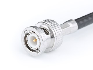
The BNC connector is a miniature quick connect/disconnect radio frequency connector used for coaxial cable.
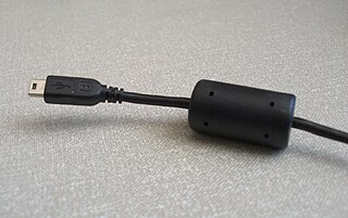
A ferrite bead is a type of choke that suppresses high-frequency electronic noise in electronic circuits.
In a radio antenna, the feed line (feedline), or feeder, is the cable or other transmission line that connects the antenna with the radio transmitter or receiver. In a transmitting antenna, it feeds the radio frequency (RF) current from the transmitter to the antenna, where it is radiated as radio waves. In a receiving antenna it transfers the tiny RF voltage induced in the antenna by the radio wave to the receiver. In order to carry RF current efficiently, feed lines are made of specialized types of cable called transmission line. The most widely used types of feed line are coaxial cable, twin-lead, ladder line, and at microwave frequencies, waveguide.

A Q meter is a piece of equipment used in the testing of radio frequency circuits. It has been largely replaced in professional laboratories by other types of impedance measuring devices, though it is still in use among radio amateurs. It was developed at Boonton Radio Corporation in Boonton, New Jersey in 1934 by William D. Loughlin.

A network analyzer is an instrument that measures the network parameters of electrical networks. Today, network analyzers commonly measure s–parameters because reflection and transmission of electrical networks are easy to measure at high frequencies, but there are other network parameter sets such as y-parameters, z-parameters, and h-parameters. Network analyzers are often used to characterize two-port networks such as amplifiers and filters, but they can be used on networks with an arbitrary number of ports.

A charge amplifier is an electronic current integrator that produces a voltage output proportional to the integrated value of the input current, or the total charge injected.
A radio transmitter or receiver is connected to an antenna which emits or receives the radio waves. The antenna feed system or antenna feed is the cable or conductor, and other associated equipment, which connects the transmitter or receiver with the antenna and makes the two devices compatible. In a radio transmitter, the transmitter generates an alternating current of radio frequency, and the feed system feeds the current to the antenna, which converts the power in the current to radio waves. In a radio receiver, the incoming radio waves excite tiny alternating currents in the antenna, and the feed system delivers this current to the receiver, which processes the signal.

A test probe is a physical device used to connect electronic test equipment to a device under test (DUT). Test probes range from very simple, robust devices to complex probes that are sophisticated, expensive, and fragile. Specific types include test prods, oscilloscope probes and current probes. A test probe is often supplied as a test lead, which includes the probe, cable and terminating connector.

A variety of types of electrical transformer are made for different purposes. Despite their design differences, the various types employ the same basic principle as discovered in 1831 by Michael Faraday, and share several key functional parts.

A line impedance stabilization network (LISN) is a device used in conducted and radiated radio-frequency emission and susceptibility tests, as specified in various electromagnetic compatibility (EMC)/EMI test standards
Radio-frequency (RF) engineering is a subset of electronic engineering involving the application of transmission line, waveguide, antenna and electromagnetic field principles to the design and application of devices that produce or utilize signals within the radio band, the frequency range of about 20 kHz up to 300 GHz.

An oscilloscope, previously called an oscillograph, and informally known as a scope or o-scope, CRO, or DSO, is a type of electronic test instrument that graphically displays varying signal voltages, usually as a calibrated two-dimensional plot of one or more signals as a function of time. The displayed waveform can then be analyzed for properties such as amplitude, frequency, rise time, time interval, distortion, and others. Originally, calculation of these values required manually measuring the waveform against the scales built into the screen of the instrument. Modern digital instruments may calculate and display these properties directly.

An LCR meter is a type of electronic test equipment used to measure the inductance (L), capacitance (C), and resistance (R) of an electronic component. In the simpler versions of this instrument the impedance was measured internally and converted for display to the corresponding capacitance or inductance value. Readings should be reasonably accurate if the capacitor or inductor device under test does not have a significant resistive component of impedance. More advanced designs measure true inductance or capacitance, as well as the equivalent series resistance of capacitors and the Q factor of inductive components.
Nominal impedance in electrical engineering and audio engineering refers to the approximate designed impedance of an electrical circuit or device. The term is applied in a number of different fields, most often being encountered in respect of: