Curve tracer

Last updated
The Type 575 Transistor-Curve Tracer displays the dynamic characteristic curves of both NPN and PNP transistors on the screen of a 5-inch cathode-ray tube. Several different transistor characteristic curves may be displayed, including the collector family in the common-base and common emitter configuration. In addition to the transistor characteristic curves, the Type 575 is used to display dynamic characteristics of a wide range of semiconductor devices." (Tektronix, Catalog, 1967) Transistor curve tracer.jpg
The Type 575 Transistor-Curve Tracer displays the dynamic characteristic curves of both NPN and PNP transistors on the screen of a 5-inch cathode-ray tube. Several different transistor characteristic curves may be displayed, including the collector family in the common-base and common emitter configuration. In addition to the transistor characteristic curves, the Type 575 is used to display dynamic characteristics of a wide range of semiconductor devices." (Tektronix, Catalog, 1967)

A curve tracer is a specialised piece of electronic test equipment used to analyze the characteristics of discrete electronic components, such as such as diodes, transistors, thyristors, and vacuum tubes. The device contains voltage and current sources that can be used to stimulate the device under test (DUT).

Contents

Operation

The function is to apply a swept (automatically continuously varying with time) voltage to two terminals of the device under test and measure the amount of current that the device permits to flow at each voltage. This so-called I-V (current versus voltage) data is either directly displayed on an oscilloscope screen, or recorded to a data file for later processing and graphing with a computer. [1] Configuration includes the maximum voltage applied, the polarity of the voltage applied (including the automatic application of both positive and negative polarities), and the resistance inserted in series with the device. The main terminal voltage can often be swept up to several thousand volts, with load currents of tens of amps available at lower voltages.

For two-terminal devices (such as diodes and DIACs), this is sufficient to fully characterize the device. The curve tracer can display all of the interesting parameters such as the diode's forward voltage, reverse leakage current, reverse breakdown voltage, and so on. For triggerable devices such as DIACs, the forward and reverse trigger voltages will be clearly displayed. The discontinuity caused by negative resistance devices (such as tunnel diodes) can also be seen. This is a method for finding electrically damaged pins on integrated circuit devices. [2]

For three-terminal devices (such as transistors) a connection to the control terminal of the device being tested is used, such as the Base or Gate terminal. For BJT transistors and other current-controlled devices, the base or other control terminal current is stepped. For FETs or other voltage-controlled devices, a stepped voltage is used instead. By sweeping the voltage through the configured range of main terminal voltages, for each voltage step of the control signal, a group of I-V curves is generated automatically. This group of curves makes it very easy to determine the gain of a transistor, or the trigger voltage of a thyristor or TRIAC.

Test Device Connection

Curve tracers usually contain convenient connection arrangements for two- or three-terminal devices, often in the form of sockets arranged to allow the plugging-in of the various common packages used for electronic components. Most curve tracers also allow the simultaneous connection of two DUTs; in this way, two DUTs can be "matched" for optimum performance in circuits (such as differential amplifiers) which depend upon the close matching of device parameters. This can be seen in the adjacent image where a toggle switch allows the rapid switching between the DUT on the left and the DUT on the right as the operator compared the respective curve families of the two devices.

I-V curves are used to characterize devices and materials through DC source-measure testing. These applications may also require the calculation of resistance and the derivation of other parameters based on I-V measurements. For example, I-V data can be used to study anomalies, locate maximum or minimum curve slopes, and perform reliability analyses. A typical application is finding a semiconductor diode's reverse bias leakage current and doing forward and reverse bias voltage sweeps and current measurements to generate its I-V curve. [3]

Kelvin sensing

Curve tracers, especially high-current models, are usually supplied with various semiconductor device test fixture adapters that have Kelvin sensing.

Capacitive balance control

Some analog curve tracers, especially sensitive low-current models, are equipped with manual control for balancing a capacitive Bridge circuit for compensating ("nulling") the stray capacitances of the test setup. This adjustment is performed by tracing the curve of the empty test setup (with all required cables, probes, adapters, and other auxiliary devices connected, but without the DUT) and adjusting the balance control until the I curve is displayed at a constant zero level.

I-V Curve Tracing

I-V curve tracing is a method of analyzing the performance of a Photovoltaic system, ideal for testing all the possible operating points of a PV module or string of modules. [4]

History

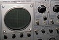
Before the introduction of semiconductors, there were vacuum tube curve tracers (e.g., Tektronix 570). Early semiconductor curve tracers themselves used vacuum tube circuits, as semiconductor devices then available could not do everything required in a curve tracer. The Tektronix model 575 curve tracer shown in the gallery was a typical early instrument.

Nowadays, curve tracers are entirely solid state and are substantially automated to ease the workload of the operator, automatically capture data, and assure the safety of the curve tracer and the DUT.

Recent developments in curve tracer systems now allow three core types of curve tracing: current-voltage (I-V), capacitance-voltage (C-V), and ultra-fast transient or pulsed current-voltage (I-V). Modern curve tracer instrument designs tend to be modular, allowing system specifiers to configure them to match the applications for which they will be used. For example, new mainframe-based curve tracer systems can be configured by specifying the number and power level of the Source Measure Units (SMUs) to be plugged into the slots in the back panel of the chassis. This modular design also provides the flexibility to incorporate other types of instrumentation to handle a wider range of applications. These mainframe-based systems typically include a self-contained PC to simplify test setup, data analysis, graphing and printing, and onboard results storage. Users of these types of systems include semiconductor researchers, device modeling engineers, reliability engineers, die-sort engineers, and process development engineers. [5]

In addition to mainframe-based systems, other curve tracer solutions are available that allow system builders to combine one or more discrete Source-Measure Units (SMUs) with a separate PC controller running curve tracer software. Discrete SMUs offer a broader range of current, voltage, and power levels than mainframe-based systems permit and allow the system to be reconfigured as test needs change. New Wizard-based user interfaces have been developed to make it easy for students or less experienced industry users to find and run the tests they need, such as the FET curve trace test. [6]

Safety

Some curve tracers, specifically those designed for high voltage or current or power devices, are capable of generating lethal voltages and currents and so pose an electrocution hazard for the operator. Modern curve tracers often contain mechanical shields and interlocks that make it more difficult for the operator to come into contact with hazardous voltages or currents. Power DUTs can become dangerously hot during testing. Inexpensive curve tracers cannot test such devices and are less likely to be lethally dangerous.

Related Research Articles

<span class="mw-page-title-main">Diode</span> Two-terminal electronic component

A diode is a two-terminal electronic component that conducts current primarily in one direction. It has low resistance in one direction, and high resistance in the other.

<span class="mw-page-title-main">Transistor</span> Solid-state electrically operated switch also used as an amplifier

A transistor is a semiconductor device used to amplify or switch electrical signals and power. It is one of the basic building blocks of modern electronics. It is composed of semiconductor material, usually with at least three terminals for connection to an electronic circuit. A voltage or current applied to one pair of the transistor's terminals controls the current through another pair of terminals. Because the controlled (output) power can be higher than the controlling (input) power, a transistor can amplify a signal. Some transistors are packaged individually, but many more in miniature form are found embedded in integrated circuits.

<span class="mw-page-title-main">Semiconductor device</span> Electronic component that exploits the electronic properties of semiconductor materials

A semiconductor device is an electronic component that relies on the electronic properties of a semiconductor material for its function. Its conductivity lies between conductors and insulators. Semiconductor devices have replaced vacuum tubes in most applications. They conduct electric current in the solid state, rather than as free electrons across a vacuum or as free electrons and ions through an ionized gas.

<span class="mw-page-title-main">Photodiode</span> Converts light into current

A photodiode is a light-sensitive semiconductor diode. It produces current when it absorbs photons.

<span class="mw-page-title-main">Bipolar junction transistor</span> Transistor that uses both electrons and holes as charge carriers

A bipolar junction transistor (BJT) is a type of transistor that uses both electrons and electron holes as charge carriers. In contrast, a unipolar transistor, such as a field-effect transistor, uses only one kind of charge carrier. A bipolar transistor allows a small current injected at one of its terminals to control a much larger current flowing between the terminals, making the device capable of amplification or switching.

<span class="mw-page-title-main">Zener diode</span> Diode that allows current to flow in the reverse direction at a specific voltage

A Zener diode is a special type of diode designed to reliably allow current to flow "backwards" when a certain set reverse voltage, known as the Zener voltage, is reached.

<span class="mw-page-title-main">Thyristor</span> Type of solid state switch

A thyristor is a solid-state semiconductor device with four layers of alternating P- and N-type materials used for high-power applications. It acts exclusively as a bistable switch, conducting when the gate receives a current trigger, and continuing to conduct until the voltage across the device is reverse-biased, or until the voltage is removed. There are two designs, differing in what triggers the conducting state. In a three-lead thyristor, a small current on its Gate lead controls the larger current of the Anode to Cathode path. In a two-lead thyristor, conduction begins when the potential difference between the Anode and Cathode themselves is sufficiently large.

<span class="mw-page-title-main">Schottky diode</span> Semiconductor diode

The Schottky diode, also known as Schottky barrier diode or hot-carrier diode, is a semiconductor diode formed by the junction of a semiconductor with a metal. It has a low forward voltage drop and a very fast switching action. The cat's-whisker detectors used in the early days of wireless and metal rectifiers used in early power applications can be considered primitive Schottky diodes.

<span class="mw-page-title-main">Varicap</span> Type of diode

In electronics, a varicap diode, varactor diode, variable capacitance diode, variable reactance diode or tuning diode is a type of diode designed to exploit the voltage-dependent capacitance of a reverse-biased p–n junction.

<span class="mw-page-title-main">Negative resistance</span> Property that an increasing voltage results in a decreasing current

In electronics, negative resistance (NR) is a property of some electrical circuits and devices in which an increase in voltage across the device's terminals results in a decrease in electric current through it.

<span class="mw-page-title-main">Electronic test equipment</span> Testing appliance for electronics systems

Electronic test equipment is used to create signals and capture responses from electronic devices under test (DUTs). In this way, the proper operation of the DUT can be proven or faults in the device can be traced. Use of electronic test equipment is essential to any serious work on electronics systems.

<span class="mw-page-title-main">DIAC</span>

The DIAC is a diode that conducts electrical current only after its breakover voltage, VBO, has been reached momentarily. Three, four, and five layer structures may be used. Behavior is similar to the voltage breakdown of a triac without a gate terminal.

<span class="mw-page-title-main">Tunnel diode</span> Diode that works using quantum tunneling effect

A tunnel diode or Esaki diode is a type of semiconductor diode that has effectively "negative resistance" due to the quantum mechanical effect called tunneling. It was invented in August 1957 by Leo Esaki, Yuriko Kurose, and Takashi Suzuki when they were working at Tokyo Tsushin Kogyo, now known as Sony. In 1973, Esaki received the Nobel Prize in Physics, jointly with Brian Josephson, for discovering the electron tunneling effect used in these diodes. Robert Noyce independently devised the idea of a tunnel diode while working for William Shockley, but was discouraged from pursuing it. Tunnel diodes were first manufactured by Sony in 1957, followed by General Electric and other companies from about 1960, and are still made in low volume today.

A power semiconductor device is a semiconductor device used as a switch or rectifier in power electronics. Such a device is also called a power device or, when used in an integrated circuit, a power IC.

<span class="mw-page-title-main">Electronic component</span> Discrete device in an electronic system

An electronic component is any basic discrete device or physical entity in an electronic system used to affect electrons or their associated fields. Electronic components are mostly industrial products, available in a singular form and are not to be confused with electrical elements, which are conceptual abstractions representing idealized electronic components and elements.

<span class="mw-page-title-main">Test probe</span>

A test probe is a physical device used to connect electronic test equipment to a device under test (DUT). Test probes range from very simple, robust devices to complex probes that are sophisticated, expensive, and fragile. Specific types include test prods, oscilloscope probes and current probes. A test probe is often supplied as a test lead, which includes the probe, cable and terminating connector.

<span class="mw-page-title-main">Shockley diode</span> Four layer semiconductor diode

The Shockley diode is a four-layer semiconductor diode, which were one of the first semiconductor devices invented. It is a PNPN diode, with alternating layers of P-type and N-type material. It is equivalent to a thyristor with a disconnected gate. Shockley diodes were manufactured and marketed by Shockley Semiconductor Laboratory in the late 1950s. The Shockley diode has a negative resistance characteristic. It was largely superseded by the diac.

A source measure unit (SMU) is a type of electronic test equipment which, as the name indicates, is capable of both sourcing and measuring at the same time.

The current injection technique is a technique developed to reduce the turn-OFF switching transient of power bipolar semiconductor devices. It was developed and published by Dr S. Eio of Staffordshire University in 2007.

A QUADRAC is a special type of thyristor which combines a DIAC and a TRIAC in a single package. The DIAC is the triggering device for the TRIAC. Thyristors are four-layer (PNPN) semiconductor devices that act as switches, rectifiers or voltage regulators in a variety of applications. When triggered, thyristors turn on and become low-resistance current paths. They remain so even after the trigger is removed, and until the current is reduced to a certain level. Diacs are bi-directional diodes that switch AC voltages and trigger triacs or silicon-controlled rectifiers (SCRs). Except for a small leakage current, diacs do not conduct until the breakover voltage is reached. Triacs are three-terminal, silicon devices that function as two SCRs configured in an inverse, parallel arrangement. They provide load current during both halves of the AC supply voltage. By combining the functions of diacs and triacs, QUADRACs eliminate the need to buy and assemble discrete parts.

References

  1. "The pypsucurvetrace curve tracer".
  2. "Curve Tracing Solutions". RTI. RTI.
  3. "Curve Tracer Measurements - Microwave Encyclopedia - Microwaves101.com". www.microwaves101.com. Archived from the original on 2005-12-17.
  4. "I-V Curve Tracing Exercises for the PV Training Lab" (PDF). Solmetric. Solmetric.
  5. Keithley Instruments, Inc. The Challenge of Integrating Three Critical Semiconductor Measurement Types into a Single Instrument Chassis. http://www.keithley.com/data?asset=52840
  6. Semiconductor Characterization Software offers parametric testing. (October 1, 2011) ThomasNet News. http://news.thomasnet.com/fullstory/Semiconductor-Characterization-Software-offers-parametric-testing-584774