
A relay is an electrically operated switch. It consists of a set of input terminals for a single or multiple control signals, and a set of operating contact terminals. The switch may have any number of contacts in multiple contact forms, such as make contacts, break contacts, or combinations thereof.
An ohmmeter is an electrical instrument that measures electrical resistance. Micro-ohmmeters make low resistance measurements. Megohmmeters measure large values of resistance. The unit of measurement for resistance is ohms (Ω).

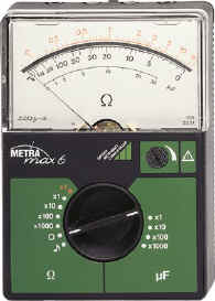
A multimeter or a multitester, also known as a VOM (volt-ohm-milliammeter), is an electronic measuring instrument that combines several measurement functions in one unit. A typical multimeter can measure voltage, current, and resistance. Analog multimeters use a microammeter with a moving pointer to display readings. Digital multimeters have a numeric display, and may also show a graphical bar representing the measured value. Digital multimeters have rendered analog multimeters obsolete, because they are now lower cost, higher precision, and more physically robust.

In electrical engineering, ground or earth is the reference point in an electrical circuit from which voltages are measured, a common return path for electric current, or a direct physical connection to the earth.
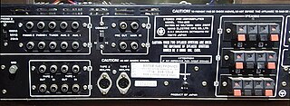
An electrical connector is an electromechanical device used to join electrical conductors and create an electrical circuit. Most electrical connectors have a gender – i.e. the male component, called a plug, connects to the female component, or socket. The connection may be removable, require a tool for assembly and removal, or serve as a permanent electrical joint between two points. An adapter can be used to join dissimilar connectors.

Electronic test equipment is used to create signals and capture responses from electronic devices under test (DUTs). In this way, the proper operation of the DUT can be proven or faults in the device can be traced. Use of electronic test equipment is essential to any serious work on electronics systems.

A residual-current device (RCD), residual-current circuit breaker (RCCB), or ground-fault circuit interrupter (GFCI) is a device that quickly breaks an electrical circuit to prevent serious harm from an ongoing electric shock. Injury may still occur in some cases, for example if a human falls after receiving a shock, or if the person touches both conductors at the same time which an RCD won't prevent.
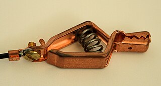
A crocodile clip is a sprung metal clip with long, serrated jaws which is used for creating a temporary electrical connection. This simple mechanical device gets its name from the resemblance of its jaws to those of an alligator or crocodile. It is used to connect an electrical cable to a battery or some other component. Functioning much like a spring-loaded clothespin, the clip's tapered, serrated jaws are forced together by a spring to grip an object. When manufactured for electronics testing and evaluation, one jaw of the clip is typically permanently crimped or soldered to a wire, or is bent to form the inner tubular contact of a ~4 mm female banana jack, enabling quick non-permanent connection between a circuit under test and laboratory equipment or to another electrical circuit. The clip is typically covered by a plastic shroud or "boot" to prevent accidental short-circuits.
In electronics, a continuity test is the checking of an electric circuit to see if current flows . A continuity test is performed by placing a small voltage across the chosen path. If electron flow is inhibited by broken conductors, damaged components, or excessive resistance, the circuit is "open".

An electronic component is any basic discrete device or physical entity in an electronic system used to affect electrons or their associated fields. Electronic components are mostly industrial products, available in a singular form and are not to be confused with electrical elements, which are conceptual abstractions representing idealized electronic components.

A cable tester is an electronic device used to verify the electrical connections in a signal cable or other wired assembly. Basic cable testers are continuity testers that verify the existence of a conductive path between ends of the cable, and verify the correct wiring of connectors on the cable. More advanced cable testers can measure the signal transmission properties of the cable such as its resistance, signal attenuation, noise and interference.

Transistor testers are instruments for testing the electrical behavior of transistors and solid-state diodes.

A test light, test lamp, voltage tester, or mains tester is a piece of electronic test equipment used to determine the presence of electricity in a piece of equipment under test. A test light is simpler and less costly than a measuring instrument such as a multimeter, and often suffices for checking for the presence of voltage on a conductor. Properly designed test lights include features to protect the user from accidental electric shock. Non-contact test lights can detect voltage on insulated conductors.
A solenoid voltmeter is a specific type of voltmeter electricians use to test electrical power circuits.
In an electric power system, a fault or fault current is any abnormal electric current. For example, a short circuit is a fault in which current bypasses the normal load. An open-circuit fault occurs if a circuit is interrupted by some failure. In three-phase systems, a fault may involve one or more phases and ground, or may occur only between phases. In a "ground fault" or "earth fault", current flows into the earth. The prospective short-circuit current of a predictable fault can be calculated for most situations. In power systems, protective devices can detect fault conditions and operate circuit breakers and other devices to limit the loss of service due to a failure.

Portable appliance testing is the name of a process in the United Kingdom, the Republic of Ireland, New Zealand and Australia by which electrical appliances are routinely checked for safety. The formal term for the process is "in-service inspection & testing of electrical equipment". Testing involves a visual inspection of the equipment and any flexible cables for good condition, and also where required, verification of earthing (grounding) continuity, and a test of the soundness of insulation between the current carrying parts, and any exposed metal that may be touched. The formal limits for pass/fail of these electrical tests vary somewhat depending on the category of equipment being tested.

An electrical outlet tester, receptacle tester, or socket tester is a small device containing a power plug and three indicator lights, used for quickly detecting some types of incorrectly-wired electrical wall outlets. The tester is easily carried in a pocket, can be used with little training, and can easily identify some common wiring problems, but can fail to indicate other types of wiring defects.

A tube tester is an electronic instrument designed to test certain characteristics of vacuum tubes. Tube testers evolved along with the vacuum tube to satisfy the demands of the time, and their evolution ended with the tube era. The first tube testers were simple units designed for specific tubes to be used in the battlefields of World War I by radio operators, so they could easily test the tubes of their communication equipment.

Megger Group Limited is a British manufacturing company that manufactures electronic test equipment and measuring instruments for electrical power applications.
An ESR meter is a two-terminal electronic measuring instrument designed and used primarily to measure the equivalent series resistance (ESR) of real capacitors; usually without the need to disconnect the capacitor from the circuit it is connected to. Other types of meters used for routine servicing, including normal capacitance meters, cannot be used to measure a capacitor's ESR, although combined meters are available which measure both ESR and out-of-circuit capacitance. A standard (DC) milliohmmeter or multimeter cannot be used to measure ESR, because a steady direct current cannot be passed through the capacitor. Most ESR meters can also be used to measure non-inductive low-value resistances, whether or not associated with a capacitor; this leads to a number of additional applications described below.
