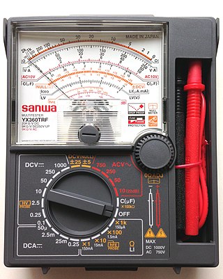
A multimeter is a measuring instrument that can measure multiple electrical properties. A typical multimeter can measure voltage, resistance, and current, in which case can be used as a voltmeter, ammeter, and ohmmeter. Some feature the measurement of additional properties such as temperature and capacitance.

In electrical engineering, ground or earth may be a reference point in an electrical circuit from which voltages are measured, a common return path for electric current, or a direct physical connection to the Earth.

Coaxial cable, or coax, is a type of electrical cable consisting of an inner conductor surrounded by a concentric conducting shield, with the two separated by a dielectric ; many coaxial cables also have a protective outer sheath or jacket. The term coaxial refers to the inner conductor and the outer shield sharing a geometric axis.

Electronic test equipment is used to create signals and capture responses from electronic devices under test (DUTs). In this way, the proper operation of the DUT can be proven or faults in the device can be traced. Use of electronic test equipment is essential to any serious work on electronics systems.
In an electrical system, a ground loop or earth loop occurs when two points of a circuit are intended to have the same ground reference potential but instead have a different potential between them. This is typically caused when enough current is flowing in the connection between the two ground points to produce a voltage drop and cause two points to be at different potentials. Current may be produced in a circular ground connection by electromagnetic induction.
In electronics, a continuity test is the checking of an electric circuit to see if current flows . A continuity test is performed by placing a small voltage across the chosen path. If electron flow is inhibited by broken conductors, damaged components, or excessive resistance, the circuit is "open".
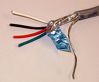
A shielded cable or screened cable is an electrical cable that has a common conductive layer around its conductors for electromagnetic shielding. This shield is usually covered by an outermost layer of the cable. Common types of cable shielding can most broadly be categorized as foil type, contraspiralling wire strands or both. A longitudinal wire may be necessary with dielectric spiral foils to short out each turn.
An earthing system or grounding system (US) connects specific parts of an electric power system with the ground, typically the Earth's conductive surface, for safety and functional purposes. The choice of earthing system can affect the safety and electromagnetic compatibility of the installation. Regulations for earthing systems vary among countries, though most follow the recommendations of the International Electrotechnical Commission (IEC). Regulations may identify special cases for earthing in mines, in patient care areas, or in hazardous areas of industrial plants.

A test light, test lamp, voltage tester, or mains tester is a piece of electronic test equipment used to determine the presence of electricity in a piece of equipment under test. A test light is simpler and less costly than a measuring instrument such as a multimeter, and often suffices for checking for the presence of voltage on a conductor. Properly designed test lights include features to protect the user from accidental electric shock. Non-contact test lights can detect voltage on insulated conductors.

A continuity tester is an item of electrical test equipment used to determine if an electrical path can be established between two points; that is if an electrical circuit can be made. The circuit under test is completely de-energized prior to connecting the apparatus.

A network analyzer is an instrument that measures the network parameters of electrical networks. Today, network analyzers commonly measure s–parameters because reflection and transmission of electrical networks are easy to measure at high frequencies, but there are other network parameter sets such as y-parameters, z-parameters, and h-parameters. Network analyzers are often used to characterize two-port networks such as amplifiers and filters, but they can be used on networks with an arbitrary number of ports.
A radio transmitter or receiver is connected to an antenna which emits or receives the radio waves. The antenna feed system or antenna feed is the cable or conductor, and other associated equipment, which connects the transmitter or receiver with the antenna and makes the two devices compatible. In a radio transmitter, the transmitter generates an alternating current of radio frequency, and the feed system feeds the current to the antenna, which converts the power in the current to radio waves. In a radio receiver, the incoming radio waves excite tiny alternating currents in the antenna, and the feed system delivers this current to the receiver, which processes the signal.

A test probe is a physical device used to connect electronic test equipment to a device under test (DUT). Test probes range from very simple, robust devices to complex probes that are sophisticated, expensive, and fragile. Specific types include test prods, oscilloscope probes and current probes. A test probe is often supplied as a test lead, which includes the probe, cable and terminating connector.
In an electric power system, a fault or fault current is any abnormal electric current. For example, a short circuit is a fault in which a live wire touches a neutral or ground wire. An open-circuit fault occurs if a circuit is interrupted by a failure of a current-carrying wire or a blown fuse or circuit breaker. In three-phase systems, a fault may involve one or more phases and ground, or may occur only between phases. In a "ground fault" or "earth fault", current flows into the earth. The prospective short-circuit current of a predictable fault can be calculated for most situations. In power systems, protective devices can detect fault conditions and operate circuit breakers and other devices to limit the loss of service due to a failure.

In electrical safety testing, portable appliance testing is a process in the United Kingdom, Ireland, New Zealand and Australia by which electrical appliances are routinely checked for safety. The formal term for the process is "in-service inspection & testing of electrical equipment". Testing involves a visual inspection of the equipment and that any flexible power cables are in good condition, and also where required, verification of earthing (grounding) continuity, and a test of the soundness of insulation between the current carrying parts, and any exposed metal that may be touched. The formal limits for pass/fail of these electrical tests vary somewhat depending on the category of equipment being tested.
In copper twisted pair wire networks, copper cable certification is achieved through a thorough series of tests in accordance with Telecommunications Industry Association (TIA) or International Organization for Standardization (ISO) standards. These tests are done using a certification-testing tool, which provide pass or fail information. While certification can be performed by the owner of the network, certification is primarily done by datacom contractors. It is this certification that allows the contractors to warranty their work.

A fiber-optic cable, also known as an optical-fiber cable, is an assembly similar to an electrical cable but containing one or more optical fibers that are used to carry light. The optical fiber elements are typically individually coated with plastic layers and contained in a protective tube suitable for the environment where the cable is used. Different types of cable are used for optical communication in different applications, for example long-distance telecommunication or providing a high-speed data connection between different parts of a building.
An optical power meter (OPM) is a device used to measure the power in an optical signal. The term usually refers to a device for testing average power in fiber optic systems. Other general purpose light power measuring devices are usually called radiometers, photometers, laser power meters, light meters or lux meters.

A tube tester is an electronic instrument designed to test certain characteristics of vacuum tubes. Tube testers evolved along with the vacuum tube to satisfy the demands of the time, and their evolution ended with the tube era. The first tube testers were simple units designed for specific tubes to be used in the battlefields of World War I by radio operators, so they could easily test the tubes of their communication equipment.
This glossary of electrical and electronics engineering is a list of definitions of terms and concepts related specifically to electrical engineering and electronics engineering. For terms related to engineering in general, see Glossary of engineering.

