Test light

Last updated
Neon test lamp for line voltages Neon Test Lamp.jpg
Neon test lamp for line voltages
Non-Contact AC Voltage Detector Voltage Tester with green light.jpg
Non-Contact AC Voltage Detector

A test light, test lamp, voltage tester, or mains tester is a piece of electronic test equipment used to determine the presence of electricity in a piece of equipment under test. A test light is simpler and less costly than a measuring instrument such as a multimeter, and often suffices for checking for the presence of voltage on a conductor. Properly designed test lights include features to protect the user from accidental electric shock. Non-contact test lights can detect voltage on insulated conductors.

Contents

Two-contact test lights

A voltage tester with three lamps to give an approximate indication of voltage magnitude Spanningszoeker.jpg
A voltage tester with three lamps to give an approximate indication of voltage magnitude

The test light is an electric lamp connected with one or two insulated wire leads. [1] Often, it takes the form of a screwdriver with the lamp connected between the tip of the screwdriver and a single lead that projects out the back of the screwdriver. By connecting the flying lead to an earth (ground) reference and touching the screwdriver tip to various points in the circuit, the presence or absence of voltage at each point can be determined, allowing simple faults to be detected and traced to their root cause. For higher voltages, a statiscope consisting of a neon glow tube mounted on a long insulating handle can be used to detect AC voltages of 2000 volts or more.

For low voltage work (for example, in automobiles), the lamp used is usually a small, low-voltage incandescent light bulb. These lamps usually are designed to operate on approximately 12 V; application of an automotive test lamp on mains voltage will destroy the lamp and may cause a short-circuit fault in the tester.

For line voltage (mains) work, the lamp is usually a small neon lamp connected in series with an appropriate ballast resistor. These lamps often can operate across a wide range of voltages from 90V up to several hundred volts. In some cases, several separate lamps are used with resistive voltage dividers arranged to allow additional lamps to strike as the applied voltage rises higher. The lamps are mounted in order from lowest voltage to highest, this minimal bar graph providing a crude indication of voltage.

Incandescent bulbs may also be used in some electronic equipment repair, and a trained technician can usually tell the approximate voltage by using the brightness as a crude indicator.

Safety

UK GS38-compliant test lamp, with separately-fused test prods and current-limiting resistor, suitable for use up to 1000V GS38 test lamp.jpg
UK GS38-compliant test lamp, with separately-fused test prods and current-limiting resistor, suitable for use up to 1000V

A hand-held test lamp necessarily puts the user in proximity to live circuits. Accidental contact with live wiring can result in a short circuit or electric shock. Inexpensive or home-made test lamps may not include sufficient protection against high-energy faults. It is customary to connect a test lamp to a known live circuit both before and after testing an unknown circuit, to check for failure of the test lamp itself.

In the UK, guidelines established by the Health and Safety Executive (HSE) provide recommendations for the construction and use of test lamps. [2] Probes must be well-insulated, with minimal exposure of live terminals, with finger guards to prevent accidental contact, and must not expose live wires if the test lamp glass bulb is broken. To limit the energy delivered in case of a short circuit, test lights must have a current-limiting fuse or current-limiting resistor and fuse. The HSE guidelines also recommend procedures to validate operation of the test light. When a known live circuit is not available, a separate proving unit that provides a known test voltage and sufficient power to illuminate the lamp is used to confirm operation of the lamp before and after testing a circuit.

Since energy to operate the test lamp is drawn from the circuit under test, some high-impedance leakage voltages may not be detectable using this type of non-amplified test equipment.

One-contact neon test lights

Neon-lamp type tester, which has no amplifier; this type requires a direct metallic contact to the circuit to be tested. Voltage test light active.jpg
Neon-lamp type tester, which has no amplifier; this type requires a direct metallic contact to the circuit to be tested.
Neon screwdriver test light in use. Current flows through a high ohm resistor and the lamp and the distributed capacitance and resistance of the user's body. LUX-Neon test light.JPG
Neon screwdriver test light in use. Current flows through a high ohm resistor and the lamp and the distributed capacitance and resistance of the user's body.

A low-cost type of test lamp only contacts one side of the circuit under test, and relies on stray capacitance and current passing through the user's body to complete the circuit. The device may have the form of a screwdriver. The tip of the tester is touched to the conductor being tested (for instance, it can be used on a wire in a switch, or inserted into a hole of an electric socket). A neon lamp takes very little current to light, and thus can use the user's body capacitance to earth ground to complete the circuit.

Screwdriver-type test lamps are very inexpensive, but cannot meet the construction requirements of UK GS 38. If the shaft is exposed, a shock hazard to the user exists, and the internal construction of the tester provides no protection against short-circuit faults. Failure of the resistor and lamp series network can put the user in direct metallic contact with the circuit under test. For example, water trapped inside the screwdriver may allow enough leakage current to shock the user. Even if an internal short circuit does not electrocute the user, the resulting electric shock may result in a fall or other injury. The lamp provides no indication below the strike voltage of the neon lamp, and so cannot detect certain hazardous leakage conditions. Since it relies on capacitance to complete the circuit, direct-current potential cannot be reliably indicated. If the user of the screwdriver is isolated from ground and capacitively coupled to other nearby live wires, a false negative may occur when testing a live circuit, and a false positive when testing a dead circuit. False negatives may also occur in brightly lit areas which make the neon glow hard to see.

Non-contact voltage detectors

Non-contact voltage tester detects the changing electric field around live wires

Amplified electronic testers (informally called electrical tester pens, test pens, or voltage detectors) rely on capacitive current only, and essentially detect the changing electric field around AC energized objects. This means that no direct metallic contact with the circuit is required. The user must touch the top of the handle to provide a ground reference (through stray capacitance to ground), at which point the indicator LED will light up or a speaker will buzz, if the conductor being tested is live. Additional energy to light the lamp and power the amplifier is supplied by a small internal battery, and does not flow through the user's body.

When the device is placed near a live conductor, a capacitive voltage divider is established, comprising the parasitic capacitance between the conductor and the sensor, and between the sensor to ground (through the user's body). [3] When the tester detects current flowing through this divider, it indicates the presence of voltage.

Some amplified testers will give a stronger indication (brighter light or louder buzz) to gauge relative strength of the detected field, thus giving some clues about the location of an energized object. Other testers give only a simple on/off indication of a detected electric field. Professional-grade testers will also have a feature to reassure the user that the battery and lamp are working.

Voltage detector pens are made for either line-voltage or lower-voltage (around 50 volt) ranges. A tester intended for mains-voltage detection may not provide any indication on lower-voltage control circuits such as those used for doorbells or HVAC control.

Unlike tong ammeters which sense changing magnetic fields, these detectors can be used even if no current is flowing through the wire in question, because they sense the alternating electric field radiating from the AC voltage on the conductor.

A non-contact tester which senses electric fields cannot detect voltage inside shielded or armored cables (a fundamental limitation due to the Faraday cage effect). Another limitation is that DC voltage cannot be detected by this method, since DC current does not pass through capacitors (in the steady state), so the tester is not activated.

These types of testers can be used on series-connected strings of mini Christmas lights to detect which bulb has failed and broken the circuit, causing the set (or a section of it) not to light. By pointing the end of the detector at the tip of each bulb, it can be determined whether it is still connected at least on one side. The first bulb which does not register is likely the one just past the problem bulb. (Burnt-out bulbs will still show as good, if there is a bypass shunt which completes the circuit.) Flipping the set's plug over and reinserting it in the outlet will cause the opposite end of the set or circuit to register instead.

Receptacle tester

North American grounded receptacle tester USA receptacle tester.jpg
North American grounded receptacle tester

A receptacle tester (outlet tester or socket tester) plugs into an outlet, and can detect some types of wiring errors. The particular error in wiring is shown by various combinations of three lights. Detectable errors include reversed hot/neutral, missing electrical ground or neutral, and others. However, leakage current through surge protective metal-oxide varistors connected between neutral and ground of a power strip can give a false indication that a ground connection exists. [4]

Continuity tester lights

A lamp and battery can be used to test for contact closure or wire continuity. Care must be taken to ensure that all circuits are completely de-energized before use of a continuity tester lamp, or the lamp will be destroyed. Sometimes a flashlight (torch) is field-modified or factory-manufactured with test leads, to allow the flashlight to be used as a continuity tester.

See also

Related Research Articles

<span class="mw-page-title-main">Fluorescent lamp</span> Lamp using fluorescence to produce light

A fluorescent lamp, or fluorescent tube, is a low-pressure mercury-vapor gas-discharge lamp that uses fluorescence to produce visible light. An electric current in the gas excites mercury vapor, which produces short-wave ultraviolet light that then causes a phosphor coating on the inside of the lamp to glow. A fluorescent lamp converts electrical energy into useful light much more efficiently than an incandescent lamp. The typical luminous efficacy of fluorescent lighting systems is 50–100 lumens per watt, several times the efficacy of incandescent bulbs with comparable light output. For comparison, the luminous efficacy of an incandescent bulb may only be 16 lumens per watt.

<span class="mw-page-title-main">Mains electricity</span> Type of lower-voltage electricity most commonly provided by utilities

Mains electricity or utility power, power grid, domestic power, and wall power, or, in some parts of Canada, hydro, is a general-purpose alternating-current (AC) electric power supply. It is the form of electrical power that is delivered to homes and businesses through the electrical grid in many parts of the world. People use this electricity to power everyday items by plugging them into a wall outlet.

<span class="mw-page-title-main">Power supply</span> Electronic device that converts or regulates electric energy and supplies it to a load

A power supply is an electrical device that supplies electric power to an electrical load. The main purpose of a power supply is to convert electric current from a source to the correct voltage, current, and frequency to power the load. As a result, power supplies are sometimes referred to as electric power converters. Some power supplies are separate standalone pieces of equipment, while others are built into the load appliances that they power. Examples of the latter include power supplies found in desktop computers and consumer electronics devices. Other functions that power supplies may perform include limiting the current drawn by the load to safe levels, shutting off the current in the event of an electrical fault, power conditioning to prevent electronic noise or voltage surges on the input from reaching the load, power-factor correction, and storing energy so it can continue to power the load in the event of a temporary interruption in the source power.

<span class="mw-page-title-main">Neon lamp</span> Light source based on gas discharge

A neon lamp is a miniature gas-discharge lamp. The lamp typically consists of a small glass capsule that contains a mixture of neon and other gases at a low pressure and two electrodes. When sufficient voltage is applied and sufficient current is supplied between the electrodes, the lamp produces an orange glow discharge. The glowing portion in the lamp is a thin region near the cathode; the larger and much longer neon signs are also glow discharges, but they use the positive column which is not present in the ordinary neon lamp. Neon glow lamps were widely used as indicator lamps in the displays of electronic instruments and appliances. They are still sometimes used for their electrical simplicity in high-voltage circuits.

<span class="mw-page-title-main">Power cord</span> Electrical cable that connects an appliance to the electricity supply via a wall socket

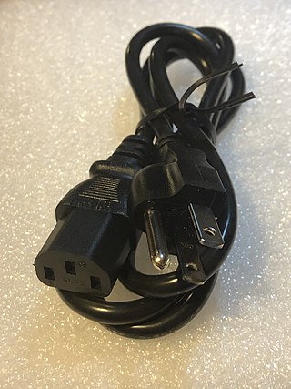
A power cord, line cord, or mains cable is an electrical cable that temporarily connects an appliance to the mains electricity supply via a wall socket or extension cord. The terms are generally used for cables using a power plug to connect to a single-phase alternating current power source at the local line voltage. The terms power cable, mains lead, flex or kettle lead are also used. A lamp cord is a light-weight, ungrounded, single-insulated two-wire cord used for small loads such as a table or floor lamp.

<span class="mw-page-title-main">Earth-leakage circuit breaker</span> Electrical safety device

An earth-leakage circuit breaker (ELCB) is a safety device used in electrical installations with high Earth impedance to prevent shock. It detects small stray voltages on the metal enclosures of electrical equipment, and interrupts the circuit if a dangerous voltage is detected. Once widely used, more recent installations instead use residual-current devices which instead detect leakage current directly.

<span class="mw-page-title-main">Isolation transformer</span> Electrical component

An isolation transformer is a transformer used to transfer electrical power from a source of alternating current (AC) power to some equipment or device while isolating the powered device from the power source, usually for safety reasons or to reduce transients and harmonics. Isolation transformers provide galvanic isolation; no conductive path is present between source and load. This isolation is used to protect against electric shock, to suppress electrical noise in sensitive devices, or to transfer power between two circuits which must not be connected. A transformer sold for isolation is often built with special insulation between primary and secondary, and is specified to withstand a high voltage between windings.

An antifuse is an electrical device that performs the opposite function to a fuse. Whereas a fuse starts with a low resistance and is designed to permanently break or open an electrically conductive path, an antifuse starts with a high resistance--an open circuit--and programming it converts it into a permanent electrically conductive path. This technology has many applications. Antifuses are best known for their use in mini-light style low-voltage Christmas tree lights.

<span class="mw-page-title-main">Plasma globe</span> Decorative electrical device

A plasma ball, plasma globe, or plasma lamp is a clear glass container filled with a mixture of various noble gases with a high-voltage electrode in the center of the container.

<span class="mw-page-title-main">Electronic component</span> Discrete device in an electronic system

An electronic component is any basic discrete electronic device or physical entity part of an electronic system used to affect electrons or their associated fields. Electronic components are mostly industrial products, available in a singular form and are not to be confused with electrical elements, which are conceptual abstractions representing idealized electronic components and elements.

<span class="mw-page-title-main">Cable tester</span> Electronic device used to verify electrical connections

A cable tester is an electronic device used to verify the electrical connections in a signal cable or other wired assembly. Basic cable testers are continuity testers that verify the existence of a conductive path between ends of the cable, and verify the correct wiring of connectors on the cable. More advanced cable testers can measure the signal transmission properties of the cable such as its resistance, signal attenuation, noise and interference.

An earthing system or grounding system (US) connects specific parts of an electric power system with the ground, typically the Earth's conductive surface, for safety and functional purposes. The choice of earthing system can affect the safety and electromagnetic compatibility of the installation. Regulations for earthing systems vary among countries, though most follow the recommendations of the International Electrotechnical Commission (IEC). Regulations may identify special cases for earthing in mines, in patient care areas, or in hazardous areas of industrial plants.

<span class="mw-page-title-main">Solenoid voltmeter</span>

A solenoid voltmeter is a specific type of voltmeter electricians use to test electrical power circuits. It uses a solenoid coil to attract a spring-loaded plunger; the movement of the plunger is calibrated in terms of approximate voltage. It is more rugged than a D'arsonval movement, but neither as sensitive nor as precise.

<span class="mw-page-title-main">Track lighting</span>

Track lighting is a method of lighting where light fixtures are attached anywhere on a continuous track device which contains electrical conductors. This is in contrast to directly routing electrical wiring to individual light positions. Tracks can either be mounted to ceilings or walls, lengthwise down beams, or crosswise across rafters or joists. They can also be hung with rods from especially high places like vaulted ceilings.

<span class="mw-page-title-main">Portable appliance testing</span> Procedure in which electrical appliances are routinely checked for safety

In electrical safety testing, portable appliance testing is a process in the United Kingdom, Ireland, New Zealand and Australia by which electrical appliances are routinely checked for safety. The formal term for the process is "in-service inspection & testing of electrical equipment". Testing involves a visual inspection of the equipment and any flexible cables for good condition, and also where required, verification of earthing (grounding) continuity, and a test of the soundness of insulation between the current carrying parts, and any exposed metal that may be touched. The formal limits for pass/fail of these electrical tests vary somewhat depending on the category of equipment being tested.

<span class="mw-page-title-main">Transformer types</span> Overview of electrical transformer types

A variety of types of electrical transformer are made for different purposes. Despite their design differences, the various types employ the same basic principle as discovered in 1831 by Michael Faraday, and share several key functional parts.

<span class="mw-page-title-main">Stray voltage</span> Electrical potential between unexpected places

Stray voltage is the occurrence of electrical potential between two objects that ideally should not have any voltage difference between them. Small voltages often exist between two grounded objects in separate locations, due to normal current flow in the power system. Large voltages can appear on the enclosures of electrical equipment due to a fault in the electrical power system, such as a failure of insulation.

<span class="mw-page-title-main">Electrical outlet tester</span> Device to verify the function of an electrical outlet

An electrical outlet tester, receptacle tester, or socket tester is a small device containing a 3-prong power plug and three indicator lights, used for quickly detecting some types of incorrectly-wired electrical wall outlets or campsite supplies. Easily carried in a pocket, it can be used with little training, and can identify some common wiring problems, but it fails to detect certain other dangerous types of wiring defects.

In electrical engineering, capacitive sensing is a technology, based on capacitive coupling, that can detect and measure anything that is conductive or has a dielectric constant different from air. Many types of sensors use capacitive sensing, including sensors to detect and measure proximity, pressure, position and displacement, force, humidity, fluid level, and acceleration. Human interface devices based on capacitive sensing, such as touchpads, can replace the computer mouse. Digital audio players, mobile phones, and tablet computers will sometimes use capacitive sensing touchscreens as input devices. Capacitive sensors can also replace mechanical buttons.

<span class="mw-page-title-main">Tube tester</span> Electronic instrument

A tube tester is an electronic instrument designed to test certain characteristics of vacuum tubes. Tube testers evolved along with the vacuum tube to satisfy the demands of the time, and their evolution ended with the tube era. The first tube testers were simple units designed for specific tubes to be used in the battlefields of World War I by radio operators, so they could easily test the tubes of their communication equipment.

References

  1. Terrel Croft, Wilford Summers American Electricians' Handbook, Eleventh Edition, McGraw Hill, 1987 ISBN   0-07-013932-6 pages 1-56 through 1-57
  2. "Guide GS 38 - PDF edition" (PDF). HSE.
  3. "What Do You Know About Capacitive Voltage Sensors?", Fluke Corp, Retrieved 6 October 2015
  4. Brian Cook Standard Check for Ungrounded Outlets Using Neon Tester Can Yield False Results, Electrical Line,(Pacific Media Publishing 2012), ISSN   1204-8011 Vol. 18 No. 2 March/April 2012 page 89