
Amplitude modulation (AM) is a modulation technique used in electronic communication, most commonly for transmitting messages with a radio wave. In amplitude modulation, the amplitude of the wave is varied in proportion to that of the message signal, such as an audio signal. This technique contrasts with angle modulation, in which either the frequency of the carrier wave is varied, as in frequency modulation, or its phase, as in phase modulation.

Analog television is the original television technology that uses analog signals to transmit video and audio. In an analog television broadcast, the brightness, colors and sound are represented by amplitude, phase and frequency of an analog signal.
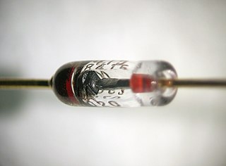
A diode is a two-terminal electronic component that conducts current primarily in one direction. It has low resistance in one direction and high resistance in the other.

An amplifier, electronic amplifier or (informally) amp is an electronic device that can increase the magnitude of a signal. It is a two-port electronic circuit that uses electric power from a power supply to increase the amplitude of a signal applied to its input terminals, producing a proportionally greater amplitude signal at its output. The amount of amplification provided by an amplifier is measured by its gain: the ratio of output voltage, current, or power to input. An amplifier is defined as a circuit that has a power gain greater than one.
A signal generator is one of a class of electronic devices that generates electrical signals with set properties of amplitude, frequency, and wave shape. These generated signals are used as a stimulus for electronic measurements, typically used in designing, testing, troubleshooting, and repairing electronic or electroacoustic devices, though it often has artistic uses as well.
Demodulation is extracting the original information-bearing signal from a carrier wave. A demodulator is an electronic circuit that is used to recover the information content from the modulated carrier wave. There are many types of modulation so there are many types of demodulators. The signal output from a demodulator may represent sound, images or binary data.

In electronics, a varicap diode, varactor diode, variable capacitance diode, variable reactance diode or tuning diode is a type of diode designed to exploit the voltage-dependent capacitance of a reverse-biased p–n junction.

Automatic gain control (AGC) is a closed-loop feedback regulating circuit in an amplifier or chain of amplifiers, the purpose of which is to maintain a suitable signal amplitude at its output, despite variation of the signal amplitude at the input. The average or peak output signal level is used to dynamically adjust the gain of the amplifiers, enabling the circuit to work satisfactorily with a greater range of input signal levels. It is used in most radio receivers to equalize the average volume (loudness) of different radio stations due to differences in received signal strength, as well as variations in a single station's radio signal due to fading. Without AGC the sound emitted from an AM radio receiver would vary to an extreme extent from a weak to a strong signal; the AGC effectively reduces the volume if the signal is strong and raises it when it is weaker. In a typical receiver the AGC feedback control signal is usually taken from the detector stage and applied to control the gain of the IF or RF amplifier stages.

An envelope detector is an electronic circuit that takes a (relatively) high-frequency signal as input and outputs the envelope of the original signal.

In radio communications, a radio receiver, also known as a receiver, a wireless, or simply a radio, is an electronic device that receives radio waves and converts the information carried by them to a usable form. It is used with an antenna. The antenna intercepts radio waves and converts them to tiny alternating currents which are applied to the receiver, and the receiver extracts the desired information. The receiver uses electronic filters to separate the desired radio frequency signal from all the other signals picked up by the antenna, an electronic amplifier to increase the power of the signal for further processing, and finally recovers the desired information through demodulation.
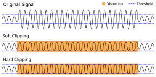
In electronics, a limiter is a circuit that allows signals below a specified input power or level to pass unaffected while attenuating (lowering) the peaks of stronger signals that exceed this threshold. Limiting is a type of dynamic range compression. Clipping is an extreme version of limiting.
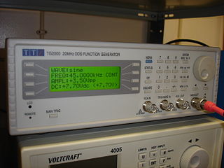
In electrical engineering, a function generator is usually a piece of electronic test equipment or software used to generate different types of electrical waveforms over a wide range of frequencies. Some of the most common waveforms produced by the function generator are the sine wave, square wave, triangular wave and sawtooth shapes. These waveforms can be either repetitive or single-shot. Another feature included on many function generators is the ability to add a DC offset. Integrated circuits used to generate waveforms may also be described as function generator ICs.

A pulse generator is either an electronic circuit or a piece of electronic test equipment used to generate rectangular pulses. Pulse generators are used primarily for working with digital circuits; related function generators are used primarily for analog circuits.

An electronic component is any basic discrete electronic device or physical entity part of an electronic system used to affect electrons or their associated fields. Electronic components are mostly industrial products, available in a singular form and are not to be confused with electrical elements, which are conceptual abstractions representing idealized electronic components and elements. A datasheet for an electronic component is a technical document that provides detailed information about the component's specifications, characteristics, and performance. Discrete circuits are made of individual electronic components that only perform one function each as packaged, which are known as discrete components, although strictly the term discrete component refers to such a component with semiconductor material such as individual transistors.

A network analyzer is an instrument that measures the network parameters of electrical networks. Today, network analyzers commonly measure s–parameters because reflection and transmission of electrical networks are easy to measure at high frequencies, but there are other network parameter sets such as y-parameters, z-parameters, and h-parameters. Network analyzers are often used to characterize two-port networks such as amplifiers and filters, but they can be used on networks with an arbitrary number of ports.
A radio transmitter or just transmitter is an electronic device which produces radio waves with an antenna. Radio waves are electromagnetic waves with frequencies between about 30 Hz and 300 GHz. The transmitter itself generates a radio frequency alternating current, which is applied to the antenna. When excited by this alternating current, the antenna radiates radio waves. Transmitters are necessary parts of all systems that use radio: radio and television broadcasting, cell phones, wireless networks, radar, two way radios like walkie talkies, radio navigation systems like GPS, remote entry systems, among numerous other uses.
Radio receiver design includes the electronic design of different components of a radio receiver which processes the radio frequency signal from an antenna in order to produce usable information such as audio. The complexity of a modern receiver and the possible range of circuitry and methods employed are more generally covered in electronics and communications engineering. The term radio receiver is understood in this article to mean any device which is intended to receive a radio signal in order to generate useful information from the signal, most notably a recreation of the so-called baseband signal which modulated the radio signal at the time of transmission in a communications or broadcast system.

In radio, a detector is a device or circuit that extracts information from a modulated radio frequency current or voltage. The term dates from the first three decades of radio (1888–1918). Unlike modern radio stations which transmit sound on an uninterrupted carrier wave, early radio stations transmitted information by radiotelegraphy. The transmitter was switched on and off to produce long or short periods of radio waves, spelling out text messages in Morse code. Therefore, early radio receivers could reproduce the Morse code "dots" and "dashes" by simply distinguishing between the presence or absence of a radio signal. The device that performed this function in the receiver circuit was called a detector. A variety of different detector devices, such as the coherer, electrolytic detector, magnetic detector and the crystal detector, were used during the wireless telegraphy era until superseded by vacuum tube technology.

In electronics, a plate detector is a vacuum tube circuit in which an amplifying tube having a control grid is operated in a non-linear region of its grid voltage versus plate current transfer characteristic, usually near plate current cutoff, to demodulate amplitude modulated carrier signal. This differs from the grid leak detector, which utilizes the non-linearity of the grid voltage versus grid current characteristic for demodulation. It also differs from the diode detector, which is a two-terminal device.
In electronics, power amplifier classes are letter symbols applied to different power amplifier types. The class gives a broad indication of an amplifier's characteristics and performance. The first three classes are related to the time period that the active amplifier device is passing current, expressed as a fraction of the period of a signal waveform applied to the input. This metric is known as conduction angle (θ). A class A amplifier is conducting through the entire period of the signal (θ=360°); Class B only for one-half the input period (θ=180°), class C for much less than half the input period (θ<180°). Class D amplifiers operate their output device in a switching manner; the fraction of the time that the device is conducting may be adjusted so a pulse-width modulation output can be obtained from the stage.