In telecommunications and radar, a Cassegrain antenna is a parabolic antenna in which the feed antenna is mounted at or behind the surface of the concave main parabolic reflector dish and is aimed at a smaller convex secondary reflector suspended in front of the primary reflector. The beam of radio waves from the feed illuminates the secondary reflector, which reflects it back to the main reflector dish, which reflects it forward again to form the desired beam. The Cassegrain design is widely used in parabolic antennas, particularly in large antennas such as those in satellite ground stations, radio telescopes, and communication satellites.

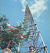
A radio telescope is a specialized antenna and radio receiver used to detect radio waves from astronomical radio sources in the sky. Radio telescopes are the main observing instrument used in radio astronomy, which studies the radio frequency portion of the electromagnetic spectrum emitted by astronomical objects, just as optical telescopes are the main observing instrument used in traditional optical astronomy which studies the light wave portion of the spectrum coming from astronomical objects. Unlike optical telescopes, radio telescopes can be used in the daytime as well as at night.
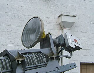
A feed horn is a small horn antenna used to couple a waveguide to e.g. a parabolic dish antenna or offset dish antenna for reception or transmission of microwave. A typical application is the use for satellite television reception with a satellite dish. In that case the feed horn can either be a separate part used together with e.g. a "low-noise block downconverter" (LNB), or more typically today is integrated into a "low-noise block feedhorn" (LNBF).
The Ku band is the portion of the electromagnetic spectrum in the microwave range of frequencies from 12 to 18 gigahertz (GHz). The symbol is short for "K-under", because it is the lower part of the original NATO K band, which was split into three bands because of the presence of the atmospheric water vapor resonance peak at 22.24 GHz, (1.35 cm) which made the center unusable for long range transmission. In radar applications, it ranges from 12 to 18 GHz according to the formal definition of radar frequency band nomenclature in IEEE Standard 521–2002.

In radio engineering, an antenna or aerial is the interface between radio waves propagating through space and electric currents moving in metal conductors, used with a transmitter or receiver. In transmission, a radio transmitter supplies an electric current to the antenna's terminals, and the antenna radiates the energy from the current as electromagnetic waves. In reception, an antenna intercepts some of the power of a radio wave in order to produce an electric current at its terminals, that is applied to a receiver to be amplified. Antennas are essential components of all radio equipment.

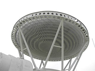
A parabolicreflector is a reflective surface used to collect or project energy such as light, sound, or radio waves. Its shape is part of a circular paraboloid, that is, the surface generated by a parabola revolving around its axis. The parabolic reflector transforms an incoming plane wave travelling along the axis into a spherical wave converging toward the focus. Conversely, a spherical wave generated by a point source placed in the focus is reflected into a plane wave propagating as a collimated beam along the axis.
A satellite dish is a dish-shaped type of parabolic antenna designed to receive or transmit information by radio waves to or from a communication satellite. The term most commonly means a dish which receives direct-broadcast satellite television from a direct broadcast satellite in geostationary orbit.

A parabolic antenna is an antenna that uses a parabolic reflector, a curved surface with the cross-sectional shape of a parabola, to direct the radio waves. The most common form is shaped like a dish and is popularly called a dish antenna or parabolic dish. The main advantage of a parabolic antenna is that it has high directivity. It functions similarly to a searchlight or flashlight reflector to direct radio waves in a narrow beam, or receive radio waves from one particular direction only. Parabolic antennas have some of the highest gains, meaning that they can produce the narrowest beamwidths, of any antenna type. In order to achieve narrow beamwidths, the parabolic reflector must be much larger than the wavelength of the radio waves used, so parabolic antennas are used in the high frequency part of the radio spectrum, at UHF and microwave (SHF) frequencies, at which the wavelengths are small enough that conveniently sized reflectors can be used.

An optical telescope is a telescope that gathers and focuses light mainly from the visible part of the electromagnetic spectrum, to create a magnified image for direct visual inspection, to make a photograph, or to collect data through electronic image sensors.

A directional antenna or beam antenna is an antenna which radiates or receives greater radio wave power in specific directions. Directional antennas can radiate radio waves in beams, when greater concentration of radiation in a certain direction is desired, or in receiving antennas receive radio waves from one specific direction only. This can increase the power transmitted to receivers in that direction, or reduce interference from unwanted sources. This contrasts with omnidirectional antennas such as dipole antennas which radiate radio waves over a wide angle, or receive from a wide angle.

A horn antenna or microwave horn is an antenna that consists of a flaring metal waveguide shaped like a horn to direct radio waves in a beam. Horns are widely used as antennas at UHF and microwave frequencies, above 300 MHz. They are used as feed antennas for larger antenna structures such as parabolic antennas, as standard calibration antennas to measure the gain of other antennas, and as directive antennas for such devices as radar guns, automatic door openers, and microwave radiometers. Their advantages are moderate directivity, broad bandwidth, low losses, and simple construction and adjustment.

A Luneburg lens is a spherically symmetric gradient-index lens. A typical Luneburg lens's refractive index n decreases radially from the center to the outer surface. They can be made for use with electromagnetic radiation from visible light to radio waves.

The Cassegrain reflector is a combination of a primary concave mirror and a secondary convex mirror, often used in optical telescopes and radio antennas, the main characteristic being that the optical path folds back onto itself, relative to the optical system's primary mirror entrance aperture. This design puts the focal point at a convenient location behind the primary mirror and the convex secondary adds a telephoto effect creating a much longer focal length in a mechanically short system.

An antenna reflector is a device that reflects electromagnetic waves. Antenna reflectors can exist as a standalone device for redirecting radio frequency (RF) energy, or can be integrated as part of an antenna assembly.

An offset dish antenna or off-axis dish antenna is a type of parabolic antenna. It is so called because the antenna feed is offset to the side of the reflector, in contrast to the common "front-feed" parabolic antenna where the feed antenna is suspended in front of the dish, on its axis. As in a front-fed parabolic dish, the feed is located at the focal point of the reflector, but the reflector is an asymmetric segment of a paraboloid, so the focus is located to the side.
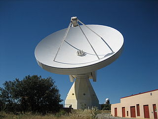
The Yebes Observatory RT40m, or ARIESXXI, is a radio telescope which is part of the observatory at Yebes, Spain. It is a 40-metre Cassegrain–Nasmyth telescope.
Focal-plane arrays (FPAs) are widely used in radio astronomy. FPAs are arrays of receivers placed at the focus of the optical system in a radio-telescope. The optical system may be a reflector or a lens. Traditional radio-telescopes have only one receiver at the focus of the telescope, but radio-telescopes are now starting to be equipped with focal plane arrays, which are of three different types: multi-beam feed arrays, bolometer arrays, and the experimental phased-array feeds.
Fresnel zone antennas are antennas that focus the signal by using the phase shifting property of the antenna surface or its shape. There are several types of Fresnel zone antennas, namely, Fresnel zone plate, offset Fresnel zone plate antennas, phase correcting reflective array or "Reflectarray" antennas and 3 Dimensional Fresnel antennas. They are a class of diffractive antennas and have been used from radio frequencies to X rays.
A lens antenna is a directional antenna that uses a shaped piece of microwave-transparent material to bend and focus microwaves by refraction, as an optical lens does for light. Typically it consists of a small feed antenna such as a patch antenna or horn antenna which radiates radio waves, with a piece of dielectric or composite material in front which functions as a converging lens to collimate the radio waves into a beam. Conversely, in a receiving antenna the lens focuses the incoming radio waves onto the feed antenna, which converts them to electric currents which are delivered to a radio receiver. They can also be fed by an array of feed antennas, called a focal plane array (FPA), to create more complicated radiation patterns.
In radio systems, many different antenna types are used whose properties are especially crafted for particular applications. Antennas can be classified in various ways. The list below groups together antennas under common operating principles, following the way antennas are classified in many engineering textbooks.