
In electrical engineering, ground or earth may be a reference point in an electrical circuit from which voltages are measured, a common return path for electric current, or a direct physical connection to the Earth.
In electrical engineering, a ground plane is an electrically conductive surface, usually connected to electrical ground.
Very low frequency or VLF is the ITU designation for radio frequencies (RF) in the range of 3–30 kHz, corresponding to wavelengths from 100 to 10 km, respectively. The band is also known as the myriameter band or myriameter wave as the wavelengths range from one to ten myriameters. Due to its limited bandwidth, audio (voice) transmission is highly impractical in this band, and therefore only low data rate coded signals are used. The VLF band is used for a few radio navigation services, government time radio stations and for secure military communication. Since VLF waves can penetrate at least 40 meters (131 ft) into saltwater, they are used for military communication with submarines.
Low frequency (LF) is the ITU designation for radio frequencies (RF) in the range of 30–300 kHz. Since its wavelengths range from 10–1 km, respectively, it is also known as the kilometre band or kilometre waves.

Medium frequency (MF) is the ITU designation for radio frequencies (RF) in the range of 300 kilohertz (kHz) to 3 megahertz (MHz). Part of this band is the medium wave (MW) AM broadcast band. The MF band is also known as the hectometer band as the wavelengths range from ten to one hectometers. Frequencies immediately below MF are denoted as low frequency (LF), while the first band of higher frequencies is known as high frequency (HF). MF is mostly used for AM radio broadcasting, navigational radio beacons, maritime ship-to-shore communication, and transoceanic air traffic control.

In radio engineering, an antenna or aerial is an electronic device that converts an alternating electric current into radio waves, or radio waves into an electric current. It is the interface between radio waves propagating through space and electric currents moving in metal conductors, used with a transmitter or receiver. In transmission, a radio transmitter supplies an electric current to the antenna's terminals, and the antenna radiates the energy from the current as electromagnetic waves. In reception, an antenna intercepts some of the power of a radio wave in order to produce an electric current at its terminals, that is applied to a receiver to be amplified. Antennas are essential components of all radio equipment.
Radiation resistance is that part of an antenna's feedpoint electrical resistance caused by the emission of radio waves from the antenna. A radio transmitter applies a radio frequency alternating current to an antenna, which radiates the energy of the current as radio waves. Because the antenna is absorbing the energy it is radiating from the transmitter, the antenna's input terminals present a resistance to the current from the transmitter.

A whip antenna is an antenna consisting of a straight flexible wire or rod. The bottom end of the whip is connected to the radio receiver or transmitter. A whip antenna is a form of monopole antenna. The antenna is designed to be flexible so that it does not break easily, and the name is derived from the whip-like motion that it exhibits when disturbed. Whip antennas for portable radios are often made of a series of interlocking telescoping metal tubes, so they can be retracted when not in use. Longer whips, made for mounting on vehicles and structures, are made of a flexible fiberglass rod around a wire core and can be up to 11 m long.

A spark-gap transmitter is an obsolete type of radio transmitter which generates radio waves by means of an electric spark. Spark-gap transmitters were the first type of radio transmitter, and were the main type used during the wireless telegraphy or "spark" era, the first three decades of radio, from 1887 to the end of World War I. German physicist Heinrich Hertz built the first experimental spark-gap transmitters in 1887, with which he proved the existence of radio waves and studied their properties.

Grimeton Radio Station in southern Sweden, close to Varberg in Halland, is an early longwave transatlantic wireless telegraphy station built in 1922–1924, that has been preserved as a historical site. From the 1920s through the 1940s it was used to transmit telegram traffic by Morse code to North America and other countries, and during World War II was Sweden's only telecommunication link with the rest of the world. It is the only remaining example of an early pre-electronic radio transmitter technology called an Alexanderson alternator. It was added to the UNESCO World Heritage List in 2004, with the statement: "Grimeton Radio Station, Varberg is an exceptionally well preserved example of a type of telecommunication centre, representing the technological achievements by the early 1920s, as well as documenting the further development over some three decades." The radio station is also an anchor site for the European Route of Industrial Heritage. The transmitter is still in operational condition, and each year on a day called Alexanderson Day is started up and transmits brief Morse code test transmissions, which can be received all over Europe.

A mast radiator is a radio mast or tower in which the metal structure itself is energized and functions as an antenna. This design, first used widely in the 1930s, is commonly used for transmitting antennas operating at low frequencies, in the LF and MF bands, in particular those used for AM radio broadcasting stations. The conductive steel mast is electrically connected to the transmitter. Its base is usually mounted on a nonconductive support to insulate it from the ground. A mast radiator is a form of monopole antenna.

A ‘T’-antenna, ‘T’-aerial, or flat-top antenna is a monopole radio antenna consisting of one or more horizontal wires suspended between two supporting radio masts or buildings and insulated from them at the ends. A vertical wire is connected to the center of the horizontal wires and hangs down close to the ground, connected to the transmitter or receiver. The shape of the antenna resembles the letter "T", hence the name. The transmitter power is applied, or the receiver is connected, between the bottom of the vertical wire and a ground connection.

A loop antenna is a radio antenna consisting of a loop or coil of wire, tubing, or other electrical conductor, that for transmitting is usually fed by a balanced power source or for receiving feeds a balanced load. Within this physical description there are two distinct types:
A monopole antenna is a class of radio antenna consisting of a straight rod-shaped conductor, often mounted perpendicularly over some type of conductive surface, called a ground plane. The driving signal from the transmitter is applied, or for receiving antennas the output signal to the receiver is taken, between the lower end of the monopole and the ground plane. One side of the antenna feedline is attached to the lower end of the monopole, and the other side is attached to the ground plane, which is often the Earth. This contrasts with a dipole antenna which consists of two identical rod conductors, with the signal from the transmitter applied between the two halves of the antenna.

The folded unipole antenna is a type of monopole mast radiator antenna used as a transmitting antenna mainly in the medium wave band for AM radio broadcasting stations. It consists of a vertical metal rod or mast mounted over and connected at its base to a grounding system consisting of buried wires. The mast is surrounded by a "skirt" of vertical wires electrically attached at or near the top of the mast. The skirt wires are connected by a metal ring near the mast base, and the feedline feeding power from the transmitter is connected between the ring and the ground.

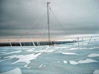
An umbrella antenna is a capacitively top-loaded wire monopole antenna, consisting in most cases of a mast fed at the ground end, to which a number of radial wires are connected at the top, sloping downwards. One side of the feedline supplying power from the transmitter is connected to the mast, and the other side to a ground (Earthing) system of radial wires buried in the earth under the antenna. They are used as transmitting antennas below 1 MHz, in the MF, LF and particularly the VLF bands, at frequencies sufficiently low that it is impractical or infeasible to build a full size quarter-wave monopole antenna. The outer end of each radial wire, sloping down from the top of the antenna, is connected by an insulator to a supporting rope or cable anchored to the ground; the radial wires can also support the mast as guy wires. The radial wires make the antenna look like the wire frame of a giant umbrella hence the name.

In radio communication, a ground dipole, also referred to as an earth dipole antenna, transmission line antenna, and in technical literature as a horizontal electric dipole (HED), is a huge, specialized type of radio antenna that radiates extremely low frequency (ELF) electromagnetic waves. It is the only type of transmitting antenna that can radiate practical amounts of power in the frequency range of 3 Hz to 3 kHz, commonly called ELF waves. A ground dipole consists of two ground electrodes buried in the earth, separated by tens to hundreds of kilometers, linked by overhead transmission lines to a power plant transmitter located between them. Alternating current electricity flows in a giant loop between the electrodes through the ground, radiating ELF waves, so the ground is part of the antenna. To be most effective, ground dipoles must be located over certain types of underground rock formations. The idea was proposed by U.S. Dept. of Defense physicist Nicholas Christofilos in 1959.
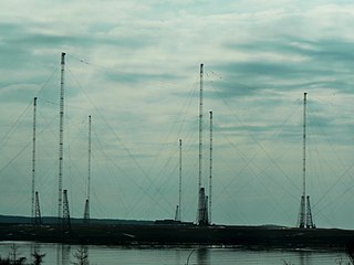
The VLF Transmitter Cutler is the United States Navy's very low frequency (VLF) shore radio station at Cutler, Maine. The station provides one-way communication to submarines of the Navy's Atlantic Fleet, both on the surface and submerged. It transmits with call sign NAA, at a frequency of 24 kHz and input power of up to 1.8 megawatts, and is one of the most powerful radio transmitters in the world.

A halo antenna, or halo, is a center-fed 1 /2 wavelength dipole antenna, which has been bent into a circle, with a break directly opposite the feed point. The dipole's ends are close, but do not touch, and their crossections may be broadened to form an air capacitor, whose spacing is used to adjust the antenna's resonant frequency. Most often mounted horizontally, this antenna's radiation is then approximately omnidirectional and horizontally polarized.
In radio systems, many different antenna types are used whose properties are especially crafted for particular applications.


