Path loss, or path attenuation, is the reduction in power density (attenuation) of an electromagnetic wave as it propagates through space. Path loss is a major component in the analysis and design of the link budget of a telecommunication system.
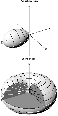
In the field of antenna design the term radiation pattern refers to the directional (angular) dependence of the strength of the radio waves from the antenna or other source.

In electronics, gain is a measure of the ability of a two-port circuit to increase the power or amplitude of a signal from the input to the output port by adding energy converted from some power supply to the signal. It is usually defined as the mean ratio of the signal amplitude or power at the output port to the amplitude or power at the input port. It is often expressed using the logarithmic decibel (dB) units. A gain greater than one, that is, amplification, is the defining property of an active component or circuit, while a passive circuit will have a gain of less than one.

In radio engineering, an antenna or aerial is an electronic device that converts an alternating electric current into radio waves (transmitting), or radio waves into an electric current (receiving). It is the interface between radio waves propagating through space and electric currents moving in metal conductors, used with a transmitter or receiver. In transmission, a radio transmitter supplies an electric current to the antenna's terminals, and the antenna radiates the energy from the current as electromagnetic waves. In reception, an antenna intercepts some of the power of a radio wave in order to produce an electric current at its terminals, that is applied to a receiver to be amplified. Antennas are essential components of all radio equipment.

A parabolic antenna is an antenna that uses a parabolic reflector, a curved surface with the cross-sectional shape of a parabola, to direct the radio waves. The most common form is shaped like a dish and is popularly called a dish antenna or parabolic dish. The main advantage of a parabolic antenna is that it has high directivity. It functions similarly to a searchlight or flashlight reflector to direct radio waves in a narrow beam, or receive radio waves from one particular direction only. Parabolic antennas have some of the highest gains, meaning that they can produce the narrowest beamwidths, of any antenna type. In order to achieve narrow beamwidths, the parabolic reflector must be much larger than the wavelength of the radio waves used, so parabolic antennas are used in the high frequency part of the radio spectrum, at UHF and microwave (SHF) frequencies, at which the wavelengths are small enough that conveniently sized reflectors can be used.

The near field and far field are regions of the electromagnetic (EM) field around an object, such as a transmitting antenna, or the result of radiation scattering off an object. Non-radiative near-field behaviors dominate close to the antenna or scatterer, while electromagnetic radiation far-field behaviors predominate at greater distances.
This is an index of articles relating to electronics and electricity or natural electricity and things that run on electricity and things that use or conduct electricity.

A directional antenna or beam antenna is an antenna which radiates or receives greater radio wave power in specific directions. Directional antennas can radiate radio waves in beams, when greater concentration of radiation in a certain direction is desired, or in receiving antennas receive radio waves from one specific direction only. This can increase the power transmitted to receivers in that direction, or reduce interference from unwanted sources. This contrasts with omnidirectional antennas such as dipole antennas which radiate radio waves over a wide angle, or receive from a wide angle.
Super high frequency (SHF) is the ITU designation for radio frequencies (RF) in the range between 3 and 30 gigahertz (GHz). This band of frequencies is also known as the centimetre band or centimetre wave as the wavelengths range from one to ten centimetres. These frequencies fall within the microwave band, so radio waves with these frequencies are called microwaves. The small wavelength of microwaves allows them to be directed in narrow beams by aperture antennas such as parabolic dishes and horn antennas, so they are used for point-to-point communication and data links and for radar. This frequency range is used for most radar transmitters, wireless LANs, satellite communication, microwave radio relay links, satellite phones, and numerous short range terrestrial data links. They are also used for heating in industrial microwave heating, medical diathermy, microwave hyperthermy to treat cancer, and to cook food in microwave ovens.
A resonator is a device or system that exhibits resonance or resonant behavior. That is, it naturally oscillates with greater amplitude at some frequencies, called resonant frequencies, than at other frequencies. The oscillations in a resonator can be either electromagnetic or mechanical. Resonators are used to either generate waves of specific frequencies or to select specific frequencies from a signal. Musical instruments use acoustic resonators that produce sound waves of specific tones. Another example is quartz crystals used in electronic devices such as radio transmitters and quartz watches to produce oscillations of very precise frequency.

Wireless power transfer is the transmission of electrical energy without wires as a physical link. In a wireless power transmission system, an electrically powered transmitter device generates a time-varying electromagnetic field that transmits power across space to a receiver device; the receiver device extracts power from the field and supplies it to an electrical load. The technology of wireless power transmission can eliminate the use of the wires and batteries, thereby increasing the mobility, convenience, and safety of an electronic device for all users. Wireless power transfer is useful to power electrical devices where interconnecting wires are inconvenient, hazardous, or are not possible.

A horn antenna or microwave horn is an antenna that consists of a flaring metal waveguide shaped like a horn to direct radio waves in a beam. Horns are widely used as antennas at UHF and microwave frequencies, above 300 MHz. They are used as feed antennas for larger antenna structures such as parabolic antennas, as standard calibration antennas to measure the gain of other antennas, and as directive antennas for such devices as radar guns, automatic door openers, and microwave radiometers. Their advantages are moderate directivity, broad bandwidth, low losses, and simple construction and adjustment.
In electromagnetics and antenna theory, the aperture of an antenna is defined as "A surface, near or on an antenna, on which it is convenient to make assumptions regarding the field values for the purpose of computing fields at external points. The aperture is often taken as that portion of a plane surface near the antenna, perpendicular to the direction of maximum radiation, through which the major part of the radiation passes."

An antenna reflector is a device that reflects electromagnetic waves. Antenna reflectors can exist as a standalone device for redirecting radio frequency (RF) energy, or can be integrated as part of an antenna assembly.
The Friis transmission formula is used in telecommunications engineering, equating the power at the terminals of a receive antenna as the product of power density of the incident wave and the effective aperture of the receiving antenna under idealized conditions given another antenna some distance away transmitting a known amount of power. The formula was presented first by Danish-American radio engineer Harald T. Friis in 1946. The formula is sometimes referenced as the Friis transmission equation.
In electronics, electric power and telecommunication, coupling is the transfer of electrical energy from one circuit to another, or between parts of a circuit. Coupling can be deliberate as part of the function of the circuit, or it may be undesirable, for instance due to coupling to stray fields. For example, energy is transferred from a power source to an electrical load by means of conductive coupling, which may be either resistive or direct coupling. An AC potential may be transferred from one circuit segment to another having a DC potential by use of a capacitor. Electrical energy may be transferred from one circuit segment to another segment with different impedance by use of a transformer; this is known as impedance matching. These are examples of electrostatic and electrodynamic inductive coupling.

A spiral antenna is a type of radio frequency antenna shaped as a spiral, first described in 1956. Archimedean spiral antennas are the most popular, while logarithmic spiral antennas are independent of frequency: the driving point impedance, radiation pattern and polarization of such antennas remain unchanged over a large bandwidth. Spiral antennas are inherently circularly polarized with low gain; antenna arrays can be used to increase the gain. Spiral antennas are reduced in size with its windings making it an extremely small structure. Lossy cavities are usually placed at the back to eliminate back lobes, because a unidirectional pattern is usually preferred in such antennas. Spiral antennas are classified into different configurations: Archimedean spiral, logarithmic spiral, square spiral, etc.
Leaky-wave antenna (LWA) belong to the more general class of traveling wave antenna, that use a traveling wave on a guiding structure as the main radiating mechanism. Traveling-wave antenna fall into two general categories, slow-wave antennas and fast-wave antennas, which are usually referred to as leaky-wave antennas.
Microwave imaging is a science which has been evolved from older detecting/locating techniques in order to evaluate hidden or embedded objects in a structure using electromagnetic (EM) waves in microwave regime. Engineering and application oriented microwave imaging for non-destructive testing is called microwave testing, see below.
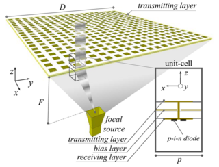
A transmitarray antenna is a phase-shifting surface (PSS), a structure capable of focusing electromagnetic radiation from a source antenna to produce a high-gain beam. Transmitarrays consist of an array of unit cells placed above a source (feeding) antenna. Phase shifts are applied to the unit cells, between elements on the receive and transmit surfaces, to focus the incident wavefronts from the feeding antenna. These thin surfaces can be used instead of a dielectric lens. Unlike phased arrays, transmitarrays do not require a feed network, so losses can be greatly reduced. Similarly, they have an advantage over reflectarrays in that feed blockage is avoided.