In classical mechanics, a harmonic oscillator is a system that, when displaced from its equilibrium position, experiences a restoring force F proportional to the displacement x:
In engineering, a transfer function of a system, sub-system, or component is a mathematical function that models the system's output for each possible input. It is widely used in electronic engineering tools like circuit simulators and control systems. In simple cases, this function can be represented as a two-dimensional graph of an independent scalar input versus the dependent scalar output. Transfer functions for components are used to design and analyze systems assembled from components, particularly using the block diagram technique, in electronics and control theory.
In signal processing, group delay and phase delay are two related ways of describing how a signal's frequency components are delayed in time when passing through a linear time-invariant (LTI) system. Phase delay describes the time shift of a sinusoidal component. Group delay describes the time shift of the envelope of a wave packet, a "pack" or "group" of oscillations centered around one frequency that travel together, formed for instance by multiplying a sine wave by an envelope.
The propagation constant of a sinusoidal electromagnetic wave is a measure of the change undergone by the amplitude and phase of the wave as it propagates in a given direction. The quantity being measured can be the voltage, the current in a circuit, or a field vector such as electric field strength or flux density. The propagation constant itself measures the dimensionless change in magnitude or phase per unit length. In the context of two-port networks and their cascades, propagation constant measures the change undergone by the source quantity as it propagates from one port to the next.
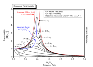
Resonance is a phenomenon that occurs when an object or system is subjected to an external force or vibration that matches its natural frequency. When this happens, the object or system absorbs energy from the external force and starts vibrating with a larger amplitude. Resonance can occur in various systems, such as mechanical, electrical, or acoustic systems, and it is often desirable in certain applications, such as musical instruments or radio receivers. However, resonance can also be detrimental, leading to excessive vibrations or even structural failure in some cases.

In electrical engineering, impedance is the opposition to alternating current presented by the combined effect of resistance and reactance in a circuit.
A resistor–capacitor circuit, or RC filter or RC network, is an electric circuit composed of resistors and capacitors. It may be driven by a voltage or current source and these will produce different responses. A first order RC circuit is composed of one resistor and one capacitor and is the simplest type of RC circuit.
A sine wave, sinusoidal wave, or sinusoid is a periodic wave whose waveform (shape) is the trigonometric sine function. In mechanics, as a linear motion over time, this is simple harmonic motion; as rotation, it corresponds to uniform circular motion. Sine waves occur often in physics, including wind waves, sound waves, and light waves, such as monochromatic radiation. In engineering, signal processing, and mathematics, Fourier analysis decomposes general functions into a sum of sine waves of various frequencies, relative phases, and magnitudes.
In signal processing, a finite impulse response (FIR) filter is a filter whose impulse response is of finite duration, because it settles to zero in finite time. This is in contrast to infinite impulse response (IIR) filters, which may have internal feedback and may continue to respond indefinitely.
In electronics engineering, frequency compensation is a technique used in amplifiers, and especially in amplifiers employing negative feedback. It usually has two primary goals: To avoid the unintentional creation of positive feedback, which will cause the amplifier to oscillate, and to control overshoot and ringing in the amplifier's step response. It is also used extensively to improve the bandwidth of single pole systems.
In mathematics and signal processing, an analytic signal is a complex-valued function that has no negative frequency components. The real and imaginary parts of an analytic signal are real-valued functions related to each other by the Hilbert transform.

In mathematics, signed frequency expands upon the concept of frequency, from just an absolute value representing how often some repeating event occurs, to also have a positive or negative sign representing one of two opposing orientations for occurrences of those events. The following examples help illustrate the concept:

In physics and engineering, a phasor is a complex number representing a sinusoidal function whose amplitude, and initial phase are time-invariant and whose angular frequency is fixed. It is related to a more general concept called analytic representation, which decomposes a sinusoid into the product of a complex constant and a factor depending on time and frequency. The complex constant, which depends on amplitude and phase, is known as a phasor, or complex amplitude, and sinor or even complexor.
In signal processing, linear phase is a property of a filter where the phase response of the filter is a linear function of frequency. The result is that all frequency components of the input signal are shifted in time by the same constant amount, which is referred to as the group delay. Consequently, there is no phase distortion due to the time delay of frequencies relative to one another.
A resistor–inductor circuit, or RL filter or RL network, is an electric circuit composed of resistors and inductors driven by a voltage or current source. A first-order RL circuit is composed of one resistor and one inductor, either in series driven by a voltage source or in parallel driven by a current source. It is one of the simplest analogue infinite impulse response electronic filters.
Ripple in electronics is the residual periodic variation of the DC voltage within a power supply which has been derived from an alternating current (AC) source. This ripple is due to incomplete suppression of the alternating waveform after rectification. Ripple voltage originates as the output of a rectifier or from generation and commutation of DC power.
Differential gain is a kind of linearity distortion that affects the amplification and transmission of analog signals. It can visibly affect color saturation in analog TV broadcasting.
Superheterodyne transmitter is a radio or TV transmitter which uses an intermediate frequency signal in addition to radio frequency signal.
In mathematics, the exponential response formula (ERF), also known as exponential response and complex replacement, is a method used to find a particular solution of a non-homogeneous linear ordinary differential equation of any order. The exponential response formula is applicable to non-homogeneous linear ordinary differential equations with constant coefficients if the function is polynomial, sinusoidal, exponential or the combination of the three. The general solution of a non-homogeneous linear ordinary differential equation is a superposition of the general solution of the associated homogeneous ODE and a particular solution to the non-homogeneous ODE. Alternative methods for solving ordinary differential equations of higher order are method of undetermined coefficients and method of variation of parameters.
In physics, a sinusoidal plane wave is a special case of plane wave: a field whose value varies as a sinusoidal function of time and of the distance from some fixed plane. It is also called a monochromatic plane wave, with constant frequency.


