A current through any conductor creates a circular magnetic field around the conductor due to Ampere's law.[3] The advantage of using the coil shape is that it increases the strength of the magnetic field produced by a given current. The magnetic fields generated by the separate turns of wire all pass through the center of the coil and add (superpose) to produce a strong field there.[3] The greater the number of turns of wire, the stronger the field produced. Conversely, a changing external magnetic flux induces a voltage in a conductor such as a wire, due to Faraday's law of induction.[3][4] The induced voltage can be increased by winding the wire into a coil because the field lines intersect the circuit multiple times.[3]
The direction of the magnetic field produced by a coil can be determined by the right hand grip rule. If the fingers of the right hand are wrapped around the magnetic core of a coil in the direction of conventional current through the wire, the thumb will point in the direction the magnetic field lines pass through the coil. The end of a magnetic core from which the field lines emerge is defined to be the North pole.
There are many different types of coils used in electric and electronic equipment.
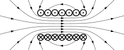
In a coil of multiple turns of wire the magnetic field of the turns adds in the center of the coil, creating a strong field. This drawing shows a cross section through the center of the coil. The crosses are wires in which current is moving into the page; the dots are wires in which current is emerging from the page.
Windings and taps
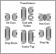
Diagram of typical transformer configurations
The wire or conductor which constitutes the coil is called the winding.[5] The hole in the center of the coil is called the core area or magnetic axis.[6] Each loop of wire is called a turn.[2] In windings where the turns touch, the wire must be insulated with a coating of nonconductive insulation to prevent the current from passing between the wire turns. This type of wire is called magnet wire and typically use polymer film insulation.[7] The winding is often wrapped around an insulating form or an iron core.[2] The ends of the wire are brought out and attached to an external circuit. Windings may have additional electrical connections along their length; these are called taps.[8] A winding that has a single tap in the center of its length is called center-tapped.[9]
Coils can have more than one winding, insulated electrically from each other. When there are two or more windings around a common magnetic axis, the windings are said to be inductively coupled or magnetically coupled.[10] A time-varying current through one winding will create a time-varying magnetic field that passes through the other winding, which will induce a time-varying voltage in the other windings. This is called a transformer.[11] The winding to which current is applied, which creates the magnetic field, is called the primary winding. The other windings are called secondary windings.
Magnetic core
Many electromagnetic coils have a magnetic core, a piece of ferromagnetic material like iron in the center to increase the magnetic field.[12] The current through the coil magnetizes the iron, and the field of the magnetized material adds to the field produced by the wire. This is called a ferromagnetic-core or iron-core coil.[13] A ferromagnetic core can increase the magnetic field and inductance of a coil by hundreds or thousands of times over what it would be without the core. A ferrite core coil is a variety of coil with a core made of ferrite, a ferrimagnetic ceramic compound.[14] Ferrite coils have lower core losses at high frequencies.
A coil with a core which forms a closed loop, possibly with some narrow air gaps, is called a closed-core coil. By providing a closed path for the magnetic field lines, this geometry minimizes the magnetic reluctance and produces the strongest magnetic field. It is often used in transformers.
A common form for closed-core coils is a toroidal core coil, in which the core has the shape of a torus or doughnut, with either a circular or rectangular cross section. This geometry has minimum leakage flux and radiates minimum electromagnetic interference (EMI).
A coil with a core which is a straight bar or other non-loop shape is called an open-core coil. This has lower magnetic field and inductance than a closed core, but is often used to prevent magnetic saturation of the core.
A coil without a ferromagnetic core is called an air-core coil.[15] This includes coils wound on plastic or other nonmagnetic forms, as well as coils which actually have empty air space inside their windings.
Types of coils
Coils can be classified by the frequency of the current they are designed to operate with:
Direct current or DC coils or electromagnets operate with a steady direct current in their windings
Electromagnets are coils that generate a magnetic field for some external use, often to exert a mechanical force on something.[16] or remove existing background fields.[17] A few specific types:
Solenoid - an electromagnet in the form of a straight hollow helix of wire
Motor and generator windings - iron core electromagnets on the rotor or stator of electric motors and generators which act on each other to either turn the shaft (motor) or generate an electric current (generator)
Field winding - an iron-core coil which generates a steady magnetic field to act on the armature winding.
Armature winding - an iron-core coil which is acted on by the magnetic field of the field winding to either create torque (motor) or induce a voltage to produce power (generator)
Degaussing coil - a coil used to demagnetize parts
Voice coil - a coil used in a moving-coil loudspeaker, suspended between the poles of a magnet. When the audio signal is passed through the coil, it vibrates, moving the attached speaker cone to create sound waves. The reverse is used in a dynamic microphone, where sound vibrations intercepted by something like a diaphragm physically transfer to a voice coil immersed in a magnetic field, and the coil's terminal ends then provide an electric analog of those vibrations.
Inductors or reactors are coils which generate a magnetic field which interacts with the coil itself, to induce a back EMF which opposes changes in current through the coil. Inductors are used as circuit elements in electrical circuits, to temporarily store energy or resist changes in current. A few types:
Choke - an inductor used to block high frequency AC while allowing through low frequency AC or DC.
Loading coil - an inductor used to add inductance to an antenna, to make it resonant, or to a cable to prevent distortion of signals.
Variometer - an adjustable inductor consisting of two coils in series, an outer stationary coil and a second one inside it which can be rotated so their magnetic axes are in the same direction or opposed.
Flyback transformer - Although called a transformer, this is actually an inductor which serves to store energy in switching power supplies and horizontal deflection circuits for CRT televisions and monitors
Saturable reactor - an iron-core inductor used to control AC power by varying the saturation of the core using a DC control voltage in an auxiliary winding.
A transformer is a device with two or more magnetically coupled windings (or sections of a single winding). A time varying current in one coil (called the primary winding) generates a magnetic field which induces a voltage in the other coil (called the secondary winding). A few types:
Autotransformer - a transformer with only one winding. Different portions of the winding, accessed with taps, act as primary and secondary windings of the transformer.
Toroidal transformer - the core is in the shape of a toroid. This is a commonly used shape as it decreases the leakage flux, resulting in less electromagnetic interference.
Induction coil or trembler coil - an early transformer which uses a vibrating interrupter mechanism to break the primary current so it can operate off of DC current.
Bifilar coil - a coil wound with two parallel, closely spaced strands. If AC currents are passed through it in the same direction, the magnetic fluxes will add, but if equal currents in opposite directions pass through the windings the opposite fluxes will cancel, resulting in zero flux in the core. So no voltage will be induced in a third winding on the core. These are used in instruments and in devices like Ground Fault Interrupters. They are also used in low inductance wirewound resistors for use at RF frequencies.
Electric machines such as motors and generators have one or more windings which interact with moving magnetic fields to convert electrical energy to mechanical energy. Often a machine will have one winding through which passes most of the power of the machine (the "armature"), and a second winding which provides the magnetic field of the rotating element ( the "field winding") which may be connected by brushes or slip rings to an external source of electric current. In an induction motor, the "field" winding of the rotor is energized by the slow relative motion between the rotating winding and the rotating magnetic field produced by the stator winding, which induces the necessary exciting current in the rotor.
These are coils used to translate time-varying magnetic fields to electric signals, and vice versa. A few types:
Sensor or pickup coils - these are used to detect external time-varying magnetic fields
Inductive sensor - a coil which senses when a magnet or iron object passes near it
Recording head - a coil which is used to create a magnetic field to write data to a magnetic storage medium, such as magnetic tape, or a hard disk. Conversely it is also used to read the data in the form of changing magnetic fields in the medium.
Querfurth, William, "Coil winding; a description of coil winding procedures, winding machines and associated equipment for the electronic industry" (2d ed.). Chicago, G. Stevens Mfg. Co., 1958.
Weymouth, F. Marten, "Drum armatures and commutators (theory and practice): a complete treatise on the theory and construction of drum winding, and of commutators for closed-coil armatures, together with a full résumé of some of the principal points involved in their design; and an exposition of armature reactions and sparking". London, "The Electrician" Printing and Publishing Co., 1893.
"Coil winding proceedings". International Coil Winding Association.
Chandler, R. H., "Coil coating review, 1970–76". Braintree, R. H. Chandler Ltd, 1977.
This page is based on this Wikipedia article Text is available under the CC BY-SA 4.0 license; additional terms may apply. Images, videos and audio are available under their respective licenses.