An electric motor is a machine that converts electrical energy into mechanical energy. Most electric motors operate through the interaction between the motor's magnetic field and electric current in a wire winding to generate force in the form of torque applied on the motor's shaft. An electric generator is mechanically identical to an electric motor, but operates in reverse, converting mechanical energy into electrical energy.
In electricity generation, a generator is a device that converts motion-based power or fuel-based power into electric power for use in an external circuit. Sources of mechanical energy include steam turbines, gas turbines, water turbines, internal combustion engines, wind turbines and even hand cranks. The first electromagnetic generator, the Faraday disk, was invented in 1831 by British scientist Michael Faraday. Generators provide nearly all the power for electrical grids.

An alternator is an electrical generator that converts mechanical energy to electrical energy in the form of alternating current. For reasons of cost and simplicity, most alternators use a rotating magnetic field with a stationary armature. Occasionally, a linear alternator or a rotating armature with a stationary magnetic field is used. In principle, any AC electrical generator can be called an alternator, but usually, the term refers to small rotating machines driven by automotive and other internal combustion engines.

A polyphase system is a means of distributing alternating-current (AC) electrical power that utilizes more than one AC phase, which refers to the phase offset value between AC in multiple conducting wires; phases may also refer to the corresponding terminals and conductors, as in color codes. Polyphase systems have two or more energized electrical conductors carrying alternating currents with a defined phase between the voltage waves in each conductor. Early systems used 4 wire two-phase with a 90° phase angle, but modern systems almost universally use three-phase voltage, with a phase angle of 120°.

A DC motor is an electrical motor that uses direct current (DC) to produce mechanical force. The most common types rely on magnetic forces produced by currents in the coils. Nearly all types of DC motors have some internal mechanism, either electromechanical or electronic, to periodically change the direction of current in part of the motor.

A rotary converter is a type of electrical machine which acts as a mechanical rectifier, inverter or frequency converter.

A field coil is an electromagnet used to generate a magnetic field in an electro-magnetic machine, typically a rotating electrical machine such as a motor or generator. It consists of a coil of wire through which the field current flows.

A rotary phase converter, abbreviated RPC, is an electrical machine that converts power from one polyphase system to another, converting through rotary motion. Typically, single-phase electric power is used to produce three-phase electric power locally to run three-phase loads in premises where only single-phase is available.

Folsom Powerhouse State Historic Park is a historical site preserving an 1895 alternating current (AC) hydroelectric power station—one of the first in the United States.

A Gramme machine, Gramme ring, Gramme magneto, or Gramme dynamo is an electrical generator that produces direct current, named for its Belgian inventor, Zénobe Gramme, and was built as either a dynamo or a magneto. It was the first generator to produce power on a commercial scale for industry. Inspired by a machine invented by Antonio Pacinotti in 1860, Gramme was the developer of a new induced rotor in form of a wire-wrapped ring and demonstrated this apparatus to the Academy of Sciences in Paris in 1871. Although popular in 19th century electrical machines, the Gramme winding principle is no longer used since it makes inefficient use of the conductors. The portion of the winding on the interior of the ring cuts no flux and does not contribute to energy conversion in the machine. The winding requires twice the number of turns and twice the number of commutator bars as an equivalent drum-wound armature.

An AC motor is an electric motor driven by an alternating current (AC). The AC motor commonly consists of two basic parts, an outside stator having coils supplied with alternating current to produce a rotating magnetic field, and an inside rotor attached to the output shaft producing a second rotating magnetic field. The rotor magnetic field may be produced by permanent magnets, reluctance saliency, or DC or AC electrical windings.
Doubly fed electric machines, Doubly fed induction generator (DFIG), or slip-ring generators, are electric motors or electric generators, where both the field magnet windings and armature windings are separately connected to equipment outside the machine.
An induction generator or asynchronous generator is a type of alternating current (AC) electrical generator that uses the principles of induction motors to produce electric power. Induction generators operate by mechanically turning their rotors faster than synchronous speed. A regular AC induction motor usually can be used as a generator, without any internal modifications. Because they can recover energy with relatively simple controls, induction generators are useful in applications such as mini hydro power plants, wind turbines, or in reducing high-pressure gas streams to lower pressure.
A brushed DC electric motor is an internally commutated electric motor designed to be run from a direct current power source and utilizing an electric brush for contact.

A dynamo is an electrical generator that creates direct current using a commutator. Dynamos were the first electrical generators capable of delivering power for industry, and the foundation upon which many other later electric-power conversion devices were based, including the electric motor, the alternating-current alternator, and the rotary converter.
In electrical engineering, electric machine is a general term for machines using electromagnetic forces, such as electric motors, electric generators, and others. They are electromechanical energy converters: an electric motor converts electricity to mechanical power while an electric generator converts mechanical power to electricity. The moving parts in a machine can be rotating or linear. While transformers are occasionally called "static electric machines", since they do not have moving parts, generally they are not considered "machines", but as electrical devices "closely related" to the electrical machines.
A permanent magnet synchronous generator is a generator where the excitation field is provided by a permanent magnet instead of a coil. The term synchronous refers here to the fact that the rotor and magnetic field rotate with the same speed, because the magnetic field is generated through a shaft-mounted permanent magnet mechanism, and current is induced into the stationary armature.

A magneto is an electrical generator that uses permanent magnets to produce periodic pulses of alternating current. Unlike a dynamo, a magneto does not contain a commutator to produce direct current. It is categorized as a form of alternator, although it is usually considered distinct from most other alternators, which use field coils rather than permanent magnets.
A flux switching alternator is a form of high-speed alternator, an AC electrical generator, intended for direct drive by a turbine. They are simple in design with the rotor containing no coils or magnets, making them rugged and capable of high rotation speeds. This makes them suitable for their only widespread use, in guided missiles.

An alternator is a type of electric generator used in modern automobiles to charge the battery and to power the electrical system when its engine is running.
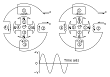
 Armature at 0 degrees.
 Armature at 90 degrees.
 Armature at 180 degrees.
 Armature at 270 degrees.
 Armature at 360 degrees.