An electric motor is an electrical machine that converts electrical energy into mechanical energy. Most electric motors operate through the interaction between the motor's magnetic field and electric current in a wire winding to generate force in the form of torque applied on the motor's shaft. An electric generator is mechanically identical to an electric motor, but operates in reverse, converting mechanical energy into electrical energy.
In electricity generation, a generator is a device that converts motion-based power or fuel-based power into electric power for use in an external circuit. Sources of mechanical energy include steam turbines, gas turbines, water turbines, internal combustion engines, wind turbines and even hand cranks. The first electromagnetic generator, the Faraday disk, was invented in 1831 by British scientist Michael Faraday. Generators provide nearly all the power for electrical grids.

A stepper motor, also known as step motor or stepping motor, is an electrical motor that rotates in a series of small angular steps, instead of continuously. Stepper motors are a type of digital actuators. A stepper motors is an electromagnetic actuator; it converts electromagnetic energy into mechanical energy to perform mechanical work.

An alternator is an electrical generator that converts mechanical energy to electrical energy in the form of alternating current. For reasons of cost and simplicity, most alternators use a rotating magnetic field with a stationary armature. Occasionally, a linear alternator or a rotating armature with a stationary magnetic field is used. In principle, any AC electrical generator can be called an alternator, but usually the term refers to small rotating machines driven by automotive and other internal combustion engines.
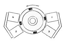
A rotating magnetic field is the resultant magnetic field produced by a system of coils symmetrically placed and supplied with polyphase currents. A rotating magnetic field can be produced by a poly-phase current or by a single phase current provided that, in the latter case, two field windings are supplied and are so designed that the two resulting magnetic fields generated thereby are out of phase.

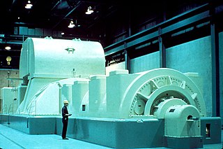
A synchronous electric motor is an AC electric motor in which, at steady state, the rotation of the shaft is synchronized with the frequency of the supply current; the rotation period is exactly equal to an integer number of AC cycles. Synchronous motors use electromagnets as the stator of the motor which create a magnetic field that rotates in time with the oscillations of the current. The rotor with permanent magnets or electromagnets turns in step with the stator field at the same rate and as a result, provides the second synchronized rotating magnet field. A synchronous motor is termed doubly fed if it is supplied with independently excited multiphase AC electromagnets on both the rotor and stator.

A brushless DC electric motor (BLDC), also known as an electronically commutated motor, is a synchronous motor using a direct current (DC) electric power supply. It uses an electronic controller to switch DC currents to the motor windings producing magnetic fields that effectively rotate in space and which the permanent magnet rotor follows. The controller adjusts the phase and amplitude of the DC current pulses to control the speed and torque of the motor. This control system is an alternative to the mechanical commutator (brushes) used in many conventional electric motors.

A DC motor is an electrical motor that uses direct current (DC) to produce mechanical force. The most common types rely on magnetic forces produced by currents in the coils. Nearly all types of DC motors have some internal mechanism, either electromechanical or electronic, to periodically change the direction of current in part of the motor.

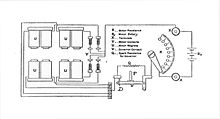
The shaded-pole motor is the original type of AC single-phase motor, dating back to at least as early as 1890. A shaded-pole motor is a small motor with either two or four poles, in which the auxiliary winding is composed of a copper ring or bar surrounding a portion of each pole to produce a weakly rotating magnetic field. When single phase AC supply is applied to the stator winding, due to shading provided to the poles, a rotating magnetic field is generated. This auxiliary single-turn winding is called a shading coil. Currents induced in this coil by the magnetic field create a second electrical phase by delaying the phase of magnetic flux change for that pole enough to provide a 2-phase rotating magnetic field. The direction of rotation is from the unshaded side to the shaded (ring) side of the pole. Since the phase angle between the shaded and unshaded sections is small, shaded-pole motors produce only a small starting torque relative to torque at full speed. Shaded-pole motors of the asymmetrical type shown are only reversible by disassembly and flipping over the stator, though some similar looking motors have small, switch-shortable auxiliary windings of thin wire instead of thick copper bars and can reverse electrically. Another method of electrical reversing involves four coils.

In electrical engineering, the armature is the winding of an electric machine which carries alternating current. The armature windings conduct AC even on DC machines, due to the commutator action or due to electronic commutation, as in brushless DC motors. The armature can be on either the rotor or the stator, depending on the type of electric machine.

The universal motor is a type of electric motor that can operate on either AC or DC power and uses an electromagnet as its stator to create its magnetic field. It is a commutated series-wound motor where the stator's field coils are connected in series with the rotor windings through a commutator. It is often referred to as an AC series motor. The universal motor is very similar to a DC series motor in construction, but is modified slightly to allow the motor to operate properly on AC power. This type of electric motor can operate well on AC because the current in both the field coils and the armature will alternate synchronously with the supply. Hence the resulting mechanical force will occur in a consistent direction of rotation, independent of the direction of applied voltage, but determined by the commutator and polarity of the field coils.
A field coil is an electromagnet used to generate a magnetic field in an electro-magnetic machine, typically a rotating electrical machine such as a motor or generator. It consists of a coil of wire through which a current flows.

An AC motor is an electric motor driven by an alternating current (AC). The AC motor commonly consists of two basic parts, an outside stator having coils supplied with alternating current to produce a rotating magnetic field, and an inside rotor attached to the output shaft producing a second rotating magnetic field. The rotor magnetic field may be produced by permanent magnets, reluctance saliency, or DC or AC electrical windings.

The rotor is a moving component of an electromagnetic system in the electric motor, electric generator, or alternator. Its rotation is due to the interaction between the windings and magnetic fields which produces a torque around the rotor's axis.
A brushed DC electric motor is an internally commutated electric motor designed to be run from a direct current power source and utilizing an electric brush for contact.

A dynamo is an electrical generator that creates direct current using a commutator. Dynamos were the first electrical generators capable of delivering power for industry, and the foundation upon which many other later electric-power conversion devices were based, including the electric motor, the alternating-current alternator, and the rotary converter.
Electromagnetic brakes or EM brakes are used to slow or stop vehicles using electromagnetic force to apply mechanical resistance (friction). They were originally called electro-mechanical brakes but over the years the name changed to "electromagnetic brakes", referring to their actuation method which is generally unrelated to modern electro-mechanical brakes. Since becoming popular in the mid-20th century, especially in trains and trams, the variety of applications and brake designs has increased dramatically, but the basic operation remains the same.
In electrical engineering, electric machine is a general term for machines using electromagnetic forces, such as electric motors, electric generators, and others. They are electromechanical energy converters: an electric motor converts electricity to mechanical power while an electric generator converts mechanical power to electricity. The moving parts in a machine can be rotating or linear. Besides motors and generators, a third category often included is transformers, which although they do not have any moving parts are also energy converters, changing the voltage level of an alternating current.

A magneto is an electrical generator that uses permanent magnets to produce periodic pulses of alternating current. Unlike a dynamo, a magneto does not contain a commutator to produce direct current. It is categorized as a form of alternator, although it is usually considered distinct from most other alternators, which use field coils rather than permanent magnets.

A telephone magneto is a hand-cranked electrical generator that uses permanent magnets to produce alternating current from a rotating armature. In early telegraphy, magnetos were used to power instruments, while in telephony they were used to generate electrical current to drive electromechanical ringers in telephone sets and activate signals on operator consoles.