
An inductor, also called a coil, choke, or reactor, is a passive two-terminal electrical component that stores energy in a magnetic field when electric current flows through it. An inductor typically consists of an insulated wire wound into a coil.

A transformer is a passive component that transfers electrical energy from one electrical circuit to another circuit, or multiple circuits. A varying current in any coil of the transformer produces a varying magnetic flux in the transformer's core, which induces a varying electromotive force (EMF) across any other coils wound around the same core. Electrical energy can be transferred between separate coils without a metallic (conductive) connection between the two circuits. Faraday's law of induction, discovered in 1831, describes the induced voltage effect in any coil due to a changing magnetic flux encircled by the coil.

In electrical engineering, impedance is the opposition to alternating current presented by the combined effect of resistance and reactance in a circuit.

Alternating current (AC) is an electric current which periodically reverses direction and changes its magnitude continuously with time, in contrast to direct current (DC), which flows only in one direction. Alternating current is the form in which electric power is delivered to businesses and residences, and it is the form of electrical energy that consumers typically use when they plug kitchen appliances, televisions, fans and electric lamps into a wall socket. The abbreviations AC and DC are often used to mean simply alternating and direct, respectively, as when they modify current or voltage.

A rectifier is an electrical device that converts alternating current (AC), which periodically reverses direction, to direct current (DC), which flows in only one direction. The reverse operation is performed by an inverter.

Electromagnetic or magnetic induction is the production of an electromotive force (emf) across an electrical conductor in a changing magnetic field.
In electrical circuits, reactance is the opposition presented to alternating current by inductance and capacitance. Along with resistance, it is one of two elements of impedance; however, while both elements involve transfer of electrical energy, no dissipation of electrical energy as heat occurs in reactance; instead, the reactance stores energy until a quarter-cycle later when the energy is returned to the circuit. Greater reactance gives smaller current for the same applied voltage.
Inductance is the tendency of an electrical conductor to oppose a change in the electric current flowing through it. The electric current produces a magnetic field around the conductor. The magnetic field strength depends on the magnitude of the electric current, and follows any changes in the magnitude of the current. From Faraday's law of induction, any change in magnetic field through a circuit induces an electromotive force (EMF) (voltage) in the conductors, a process known as electromagnetic induction. This induced voltage created by the changing current has the effect of opposing the change in current. This is stated by Lenz's law, and the voltage is called back EMF.

In electrical engineering, impedance matching is the practice of designing or adjusting the input impedance or output impedance of an electrical device for a desired value. Often, the desired value is selected to maximize power transfer or minimize signal reflection. For example, impedance matching typically is used to improve power transfer from a radio transmitter via the interconnecting transmission line to the antenna. Signals on a transmission line will be transmitted without reflections if the transmission line is terminated with a matching impedance.

A gyrator is a passive, linear, lossless, two-port electrical network element proposed in 1948 by Bernard D. H. Tellegen as a hypothetical fifth linear element after the resistor, capacitor, inductor and ideal transformer. Unlike the four conventional elements, the gyrator is non-reciprocal. Gyrators permit network realizations of two-(or-more)-port devices which cannot be realized with just the four conventional elements. In particular, gyrators make possible network realizations of isolators and circulators. Gyrators do not however change the range of one-port devices that can be realized. Although the gyrator was conceived as a fifth linear element, its adoption makes both the ideal transformer and either the capacitor or inductor redundant. Thus the number of necessary linear elements is in fact reduced to three. Circuits that function as gyrators can be built with transistors and op-amps using feedback.

An LC circuit, also called a resonant circuit, tank circuit, or tuned circuit, is an electric circuit consisting of an inductor, represented by the letter L, and a capacitor, represented by the letter C, connected together. The circuit can act as an electrical resonator, an electrical analogue of a tuning fork, storing energy oscillating at the circuit's resonant frequency.
In the power systems analysis field of electrical engineering, a per-unit system is the expression of system quantities as fractions of a defined base unit quantity. Calculations are simplified because quantities expressed as per-unit do not change when they are referred from one side of a transformer to the other. This can be a pronounced advantage in power system analysis where large numbers of transformers may be encountered. Moreover, similar types of apparatus will have the impedances lying within a narrow numerical range when expressed as a per-unit fraction of the equipment rating, even if the unit size varies widely. Conversion of per-unit quantities to volts, ohms, or amperes requires a knowledge of the base that the per-unit quantities were referenced to. The per-unit system is used in power flow, short circuit evaluation, motor starting studies etc.

An autotransformer is an electrical transformer with only one winding. The "auto" prefix refers to the single coil acting alone. In an autotransformer, portions of the same winding act as both the primary winding and secondary winding sides of the transformer. In contrast, an ordinary transformer has separate primary and secondary windings that are not connected by an electrically conductive path. between them.

In electrical engineering, three-phase electric power systems have at least three conductors carrying alternating voltages that are offset in time by one-third of the period. A three-phase system may be arranged in delta (∆) or star (Y). A wye system allows the use of two different voltages from all three phases, such as a 230/400 V system which provides 230 V between the neutral and any one of the phases, and 400 V across any two phases. A delta system arrangement provides only one voltage, but it has a greater redundancy as it may continue to operate normally with one of the three supply windings offline, albeit at 57.7% of total capacity. Harmonic current in the neutral may become very large if nonlinear loads are connected.

A variety of types of electrical transformer are made for different purposes. Despite their design differences, the various types employ the same basic principle as discovered in 1831 by Michael Faraday, and share several key functional parts.
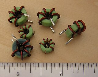
Toroidal inductors and transformers are inductors and transformers which use magnetic cores with a toroidal shape. They are passive electronic components, consisting of a circular ring or donut shaped magnetic core of ferromagnetic material such as laminated iron, iron powder, or ferrite, around which wire is wound.

The gyrator–capacitor model - sometimes also the capacitor-permeance model - is a lumped-element model for magnetic circuits, that can be used in place of the more common resistance–reluctance model. The model makes permeance elements analogous to electrical capacitance rather than electrical resistance. Windings are represented as gyrators, interfacing between the electrical circuit and the magnetic model.
A system of skew coordinates is a curvilinear coordinate system where the coordinate surfaces are not orthogonal, in contrast to orthogonal coordinates.
A blocked rotor test is conducted on an induction motor. It is also known as short-circuit test, locked rotor test or stalled torque test. From this test, short-circuit current at normal voltage, power factor on short circuit, total leakage reactance, and starting torque of the motor can be found. It is very important to know a motor's starting torque since if it is not enough to overcome the initial friction of its intended load then it will remain stationary while drawing an excessive current and rapidly overheat. The test may be conducted at lower voltage because at the normal voltage the current through the windings would be high enough to rapidly overheat and damage them. The test may still be conducted at full voltage if it is brief enough to avoid overheating the windings or overloading the starting circuits, but requires much more care to be taken while performing the test. The blocked rotor torque test is less significant on wound-rotor motors because the starting torque of these wound-rotor motors depend upon the external resistance added. However, it may still be used to characterise the motor.

The purpose of a short-circuit test is to determine the series branch parameters of the equivalent circuit of a transformer.


