
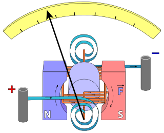
An ammeter is an instrument used to measure the current in a circuit. Electric currents are measured in amperes (A), hence the name. For direct measurement, the ammeter is connected in series with the circuit in which the current is to be measured. An ammeter usually has low resistance so that it does not cause a significant voltage drop in the circuit being measured.

A transformer is a passive component that transfers electrical energy from one electrical circuit to another circuit, or multiple circuits. A varying current in any coil of the transformer produces a varying magnetic flux in the transformer's core, which induces a varying electromotive force (EMF) across any other coils wound around the same core. Electrical energy can be transferred between separate coils without a metallic (conductive) connection between the two circuits. Faraday's law of induction, discovered in 1831, describes the induced voltage effect in any coil due to a changing magnetic flux encircled by the coil.
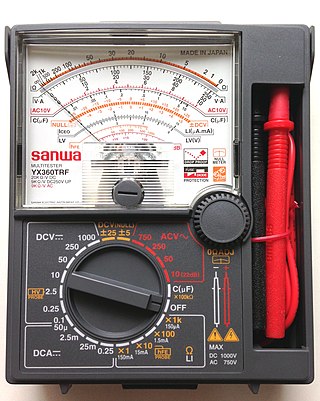
A multimeter is a measuring instrument that can measure multiple electrical properties. A typical multimeter can measure voltage, resistance, and current, in which case can be used as a voltmeter, ammeter, and ohmmeter. Some feature the measurement of additional properties such as temperature and capacitance.

A Rogowski coil, named after Walter Rogowski, is an electrical device for measuring alternating current (AC) or high-speed current pulses. It sometimes consists of a helical coil of wire with the lead from one end returning through the centre of the coil to the other end so that both terminals are at the same end of the coil. This approach is sometimes referred to as a counter-wound Rogowski.

A balun is an electrical device that allows balanced and unbalanced lines to be interfaced without disturbing the impedance arrangement of either line. A balun can take many forms and may include devices that also transform impedances but need not do so. Sometimes, in the case of transformer baluns, they use magnetic coupling but need not do so. Common-mode chokes are also used as baluns and work by eliminating, rather than rejecting, common mode signals.

A voltage regulator is a system designed to automatically maintain a constant voltage. It may use a simple feed-forward design or may include negative feedback. It may use an electromechanical mechanism, or electronic components. Depending on the design, it may be used to regulate one or more AC or DC voltages.

The linear variable differential transformer (LVDT) is a type of electrical transformer used for measuring linear displacement (position). A counterpart to this device that is used for measuring rotary displacement is called a rotary variable differential transformer (RVDT).
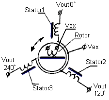
A synchro is, in effect, a transformer whose primary-to-secondary coupling may be varied by physically changing the relative orientation of the two windings. Synchros are often used for measuring the angle of a rotating machine such as an antenna platform or transmitting rotation. In its general physical construction, it is much like an electric motor. The primary winding of the transformer, fixed to the rotor, is excited by an alternating current, which by electromagnetic induction, causes voltages to appear between the Y-connected secondary windings fixed at 120 degrees to each other on the stator. The voltages are measured and used to determine the angle of the rotor relative to the stator.

An autotransformer is an electrical transformer with only one winding. The "auto" prefix refers to the single coil acting alone. In an autotransformer, portions of the same winding act as both the primary winding and secondary winding sides of the transformer. In contrast, an ordinary transformer has separate primary and secondary windings that are not connected by an electrically conductive path. between them.

A zigzag transformer winding is a special-purpose transformer winding with a zigzag or "interconnected star" connection, such that each output is the vector sum of two (2) phases offset by 120°. It is used as a grounding transformer, creating a missing neutral connection from an ungrounded 3-phase system to permit the grounding of that neutral to an earth reference point; to perform harmonic mitigation, as they can suppress triplet harmonic currents; to supply 3-phase power as an autotransformer ; and to supply non-standard, phase-shifted, 3-phase power.

A current transformer (CT) is a type of transformer that is used to reduce or multiply an alternating current (AC). It produces a current in its secondary which is proportional to the current in its primary.
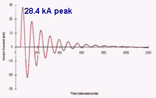
Inrush current, input surge current, or switch-on surge is the maximal instantaneous input current drawn by an electrical device when first turned on. Alternating-current electric motors and transformers may draw several times their normal full-load current when first energized, for a few cycles of the input waveform. Power converters also often have inrush currents much higher than their steady-state currents, due to the charging current of the input capacitance. The selection of over-current-protection devices such as fuses and circuit breakers is made more complicated when high inrush currents must be tolerated. The over-current protection must react quickly to overload or short-circuit faults but must not interrupt the circuit when the inrush current flows.

In electrical and electronic engineering, a current clamp, also known as current probe, is an electrical device with jaws which open to allow clamping around an electrical conductor. This allows measurement of the current in a conductor without the need to make physical contact with it, or to disconnect it for insertion through the probe.

In electrical engineering, dot marking convention, or alphanumeric marking convention, or both, can be used to denote the same relative instantaneous polarity of two mutually inductive components such as between transformer windings. These markings may be found on transformer cases beside terminals, winding leads, nameplates, schematic and wiring diagrams.

A test probe is a physical device used to connect electronic test equipment to a device under test (DUT). Test probes range from very simple, robust devices to complex probes that are sophisticated, expensive, and fragile. Specific types include test prods, oscilloscope probes and current probes. A test probe is often supplied as a test lead, which includes the probe, cable and terminating connector.

A variety of types of electrical transformer are made for different purposes. Despite their design differences, the various types employ the same basic principle as discovered in 1831 by Michael Faraday, and share several key functional parts.

In electrical engineering, a protective relay is a relay device designed to trip a circuit breaker when a fault is detected. The first protective relays were electromagnetic devices, relying on coils operating on moving parts to provide detection of abnormal operating conditions such as over-current, overvoltage, reverse power flow, over-frequency, and under-frequency.

Voltage transformers (VT), also called potential transformers (PT), are a parallel-connected type of instrument transformer. They are designed to present a negligible load to the supply being measured and have an accurate voltage ratio and phase relationship to enable accurate secondary connected metering.
In electrical engineering, current sensing is any one of several techniques used to measure electric current. The measurement of current ranges from picoamps to tens of thousands of amperes. The selection of a current sensing method depends on requirements such as magnitude, accuracy, bandwidth, robustness, cost, isolation or size. The current value may be directly displayed by an instrument, or converted to digital form for use by a monitoring or control system.
This glossary of electrical and electronics engineering is a list of definitions of terms and concepts related specifically to electrical engineering and electronics engineering. For terms related to engineering in general, see Glossary of engineering.


