
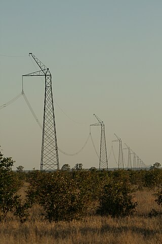
Three-phase electric power is a common type of alternating current (AC) used in electricity generation, transmission, and distribution. It is a type of polyphase system employing three wires and is the most common method used by electrical grids worldwide to transfer power.

In electrical engineering, ground or earth may be a reference point in an electrical circuit from which voltages are measured, a common return path for electric current, or a direct physical connection to the Earth.
Single-wire earth return (SWER) or single-wire ground return is a single-wire transmission line which supplies single-phase electric power from an electrical grid to remote areas at lowest cost. The earth is used as the return path for the current, to avoid the need for a second wire to act as a return path.
Electrical wiring in North America follows the regulations and standards applicable at the installation location. It is also designed to provide proper function, and is also influenced by history and traditions of the location installation.

An earth-leakage circuit breaker (ELCB) is a safety device used in electrical installations with high Earth impedance to prevent shock. It detects small stray voltages on the metal enclosures of electrical equipment, and interrupts the circuit if a dangerous voltage is detected. Once widely used, more recent installations instead use residual-current devices which instead detect leakage current directly.

A split-phase or single-phase three-wire system is a type of single-phase electric power distribution. It is the alternating current (AC) equivalent of the original Edison Machine Works three-wire direct-current system. Its primary advantage is that, for a given capacity of a distribution system, it saves conductor material over a single-ended single-phase system.

In electrical engineering, ground and neutral are circuit conductors used in alternating current (AC) electrical systems. The neutral conductor receives and returns alternating current to the supply during normal operation of the circuit; to limit the effects of leakage current from higher-voltage systems, the neutral conductor is often connected to earth ground at the point of supply. By contrast, a ground conductor is not intended to carry current for normal operation, but instead connects exposed metallic components to earth ground. A ground conductor only carries significant current if there is a circuit fault that would otherwise energize exposed conductive parts and present a shock hazard. In that case, circuit protection devices may detect a fault to a grounded metal enclosure and automatically de-energize the circuit, or may provide a warning of a ground fault.

In electrical engineering, an autotransformer is an electrical transformer with only one winding. The "auto" prefix refers to the single coil acting alone. In an autotransformer, portions of the same winding act as both the primary winding and secondary winding sides of the transformer. In contrast, an ordinary transformer has separate primary and secondary windings that are not connected by an electrically conductive path between them.
The prospective short-circuit current (PSCC), available fault current, or short-circuit making current is the highest electric current which can exist in a particular electrical system under short-circuit conditions. It is determined by the voltage and impedance of the supply system. It is of the order of a few thousand amperes for a standard domestic mains electrical installation, but may be as low as a few milliamperes in a separated extra-low voltage (SELV) system or as high as hundreds of thousands of amps in large industrial power systems. The term is used in electrical engineering rather than electronics.

A zigzag transformer winding is a special-purpose transformer winding with a zigzag or "interconnected star" connection, such that each output is the vector sum of two (2) phases offset by 120°. It is used as a grounding transformer, creating a missing neutral connection from an ungrounded 3-phase system to permit the grounding of that neutral to an earth reference point; to perform harmonic mitigation, as they can suppress triplet harmonic currents; to supply 3-phase power as an autotransformer ; and to supply non-standard, phase-shifted, 3-phase power.

A current transformer (CT) is a type of transformer that reduces or multiplies alternating current (AC), producing a current in its secondary which is proportional to the current in its primary.

An HVDC converter station is a specialised type of substation which forms the terminal equipment for a high-voltage direct current (HVDC) transmission line. It converts direct current to alternating current or the reverse. In addition to the converter, the station usually contains:
A distribution transformer or service transformer provides a final voltage transformation in the electric power distribution system, stepping down the voltage used in the distribution lines to the level used by the customer. The invention of a practical, efficient transformer made AC power distribution feasible; a system using distribution transformers was demonstrated as early as 1882.
An earthing system or grounding system (US) connects specific parts of an electric power system with the ground, typically the equipment's conductive surface, for safety and functional purposes. The choice of earthing system can affect the safety and electromagnetic compatibility of the installation. Regulations for earthing systems vary among countries, though most follow the recommendations of the International Electrotechnical Commission (IEC). Regulations may identify special cases for earthing in mines, in patient care areas, or in hazardous areas of industrial plants.

In electric power distribution, a service drop is an overhead electrical line running from a utility pole, to a customer's building or other premises. It is the point where electric utilities provide power to their customers. The customer connection to an underground distribution system is usually called a "service lateral". Conductors of a service drop or lateral are usually owned and maintained by the utility company, but some industrial drops are installed and owned by the customer.
In electrical engineering, a vector group, officially called a connection symbol, is the International Electrotechnical Commission (IEC) method of categorizing the high voltage (HV) windings and low voltage (LV) winding configurations of three-phase transformers. The vector group designation indicates the windings configurations and the difference in phase angle between them. For example, a star HV winding and delta LV winding with a 30-degree lead is denoted as Yd11.
A delta-wye transformer is a type of three-phase electric power transformer design that employs delta-connected windings on its primary and wye/star connected windings on its secondary. A neutral wire can be provided on wye output side. It can be a single three-phase transformer, or built from three independent single-phase units. An equivalent term is delta-star transformer.
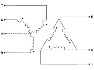
A Scott-T transformer or Scott connection is a type of circuit used to produce two-phase electric power from a three-phase source, or vice versa. The Scott connection evenly distributes a balanced load between the phases of the source. The Scott three-phase transformer was invented by Westinghouse engineer Charles F. Scott in the late 1890s to bypass Thomas Edison's more expensive rotary converter and thereby permit two-phase generator plants to drive three-phase motors.
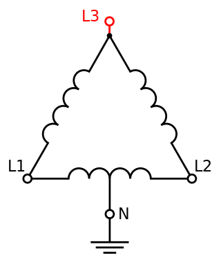
High-leg delta is a type of electrical service connection for three-phase electric power installations. It is used when both single and three-phase power is desired to be supplied from a three phase transformer. The three-phase power is connected in the delta configuration, and the center point of one phase is grounded. This creates both a split-phase single-phase supply and three-phase. It is sometimes called orange leg because the L3 wire is required to be color-coded orange in the United States. By convention, the high leg is usually set in the center lug in the involved panel, regardless of the L1–L2–L3 designation at the transformer.

Various types of electrical transformer are made for different purposes. Despite their design differences, the various types employ the same basic principle as discovered in 1831 by Michael Faraday, and share several key functional parts.


