Related Research Articles

An electromagnetic coil is an electrical conductor such as a wire in the shape of a coil. Electromagnetic coils are used in electrical engineering, in applications where electric currents interact with magnetic fields, in devices such as electric motors, generators, inductors, electromagnets, transformers, sensor coils such as in medical FMRi imaging devices with coils going upto 3-7 and even higher Tesla. Either an electric current is passed through the wire of the coil to generate a magnetic field, or conversely, an external time-varying magnetic field through the interior of the coil generates an EMF (voltage) in the conductor.

An inductor, also called a coil, choke, or reactor, is a passive two-terminal electrical component that stores energy in a magnetic field when electric current flows through it. An inductor typically consists of an insulated wire wound into a coil.

In electrical engineering, a transformer is a passive component that transfers electrical energy from one electrical circuit to another circuit, or multiple circuits. A varying current in any coil of the transformer produces a varying magnetic flux in the transformer's core, which induces a varying electromotive force (EMF) across any other coils wound around the same core. Electrical energy can be transferred between separate coils without a metallic (conductive) connection between the two circuits. Faraday's law of induction, discovered in 1831, describes the induced voltage effect in any coil due to a changing magnetic flux encircled by the coil.

Electromagnetic or magnetic induction is the production of an electromotive force (emf) across an electrical conductor in a changing magnetic field.

A printed circuit board (PCB), also called printed wiring board (PWB), is a medium used to connect or "wire" components to one another in a circuit. It takes the form of a laminated sandwich structure of conductive and insulating layers: each of the conductive layers is designed with a pattern of traces, planes and other features etched from one or more sheet layers of copper laminated onto and/or between sheet layers of a non-conductive substrate. Electrical components may be fixed to conductive pads on the outer layers in the shape designed to accept the component's terminals, generally by means of soldering, to both electrically connect and mechanically fasten them to it. Another manufacturing process adds vias, plated-through holes that allow interconnections between layers.

An electric motor is an electrical machine that converts electrical energy into mechanical energy. Most electric motors operate through the interaction between the motor's magnetic field and electric current in a wire winding to generate force in the form of torque applied on the motor's shaft. An electric generator is mechanically identical to an electric motor, but operates in reverse, converting mechanical energy into electrical energy.
An electromagnet is a type of magnet in which the magnetic field is produced by an electric current. Electromagnets usually consist of wire wound into a coil. A current through the wire creates a magnetic field which is concentrated in the hole in the center of the coil. The magnetic field disappears when the current is turned off. The wire turns are often wound around a magnetic core made from a ferromagnetic or ferrimagnetic material such as iron; the magnetic core concentrates the magnetic flux and makes a more powerful magnet.

In electromagnetism, an eddy current is a loop of electric current induced within conductors by a changing magnetic field in the conductor according to Faraday's law of induction or by the relative motion of a conductor in a magnetic field. Eddy currents flow in closed loops within conductors, in planes perpendicular to the magnetic field. They can be induced within nearby stationary conductors by a time-varying magnetic field created by an AC electromagnet or transformer, for example, or by relative motion between a magnet and a nearby conductor. The magnitude of the current in a given loop is proportional to the strength of the magnetic field, the area of the loop, and the rate of change of flux, and inversely proportional to the resistivity of the material. When graphed, these circular currents within a piece of metal look vaguely like eddies or whirlpools in a liquid.

A Bitter electromagnet or Bitter solenoid is a type of electromagnet invented in 1933 by American physicist Francis Bitter used in scientific research to create extremely strong magnetic fields. Bitter electromagnets have been used to achieve the strongest continuous manmade magnetic fields on earth―up to 45 teslas, as of 2011.

A magnetic circuit is made up of one or more closed loop paths containing a magnetic flux. The flux is usually generated by permanent magnets or electromagnets and confined to the path by magnetic cores consisting of ferromagnetic materials like iron, although there may be air gaps or other materials in the path. Magnetic circuits are employed to efficiently channel magnetic fields in many devices such as electric motors, generators, transformers, relays, lifting electromagnets, SQUIDs, galvanometers, and magnetic recording heads.

A current transformer (CT) is a type of transformer that is used to reduce or multiply an alternating current (AC). It produces a current in its secondary which is proportional to the current in its primary.
A magnetic core is a piece of magnetic material with a high magnetic permeability used to confine and guide magnetic fields in electrical, electromechanical and magnetic devices such as electromagnets, transformers, electric motors, generators, inductors, loudspeakers, magnetic recording heads, and magnetic assemblies. It is made of ferromagnetic metal such as iron, or ferrimagnetic compounds such as ferrites. The high permeability, relative to the surrounding air, causes the magnetic field lines to be concentrated in the core material. The magnetic field is often created by a current-carrying coil of wire around the core.

A welding power supply is a device that provides or modulates an electric current to perform arc welding. There are multiple arc welding processes ranging from Shielded Metal Arc Welding (SMAW) to inert shielding gas like Gas metal arc welding (GMAW) or Gas tungsten arc welding (GTAW). Welding power supplies primarily serve as devices that allow a welder to exercise control over whether current is alternating current (AC) or direct current (DC), as well as the amount of current and voltage.

Electrical steel is speciality steel used in the cores of electromagnetic devices such as motors, generators, and transformers because it reduces power loss. It is an iron alloy with silicon as the main additive element. The exact formulation is tailored to produce specific magnetic properties: small hysteresis area resulting in low power loss per cycle, low core loss, and high permeability.
Induction hardening is a type of surface hardening in which a metal part is induction-heated and then quenched. The quenched metal undergoes a martensitic transformation, increasing the hardness and brittleness of the part. Induction hardening is used to selectively harden areas of a part or assembly without affecting the properties of the part as a whole.

Magnet wire or enameled wire is a copper or aluminium wire coated with a very thin layer of insulation. It is used in the construction of transformers, inductors, motors, generators, speakers, hard disk head actuators, electromagnets, electric guitar pickups, and other applications that require tight coils of insulated wire.

A variety of types of electrical transformer are made for different purposes. Despite their design differences, the various types employ the same basic principle as discovered in 1831 by Michael Faraday, and share several key functional parts.
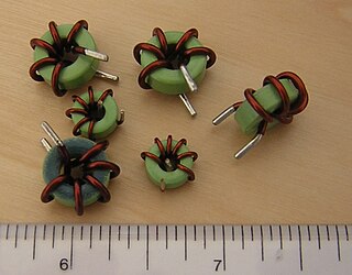
Toroidal inductors and transformers are inductors and transformers which use magnetic cores with a toroidal shape. They are passive electronic components, consisting of a circular ring or donut shaped magnetic core of ferromagnetic material such as laminated iron, iron powder, or ferrite, around which wire is wound.

Electrical insulation papers are paper types that are used as electrical insulation in many applications due to pure cellulose having outstanding electrical properties. Cellulose is a good insulator and is also polar, having a dielectric constant significantly greater than one. Electrical paper products are classified by their thickness, with tissue considered papers less than 1.5 mils (0.0381 mm) thickness, and board considered more than 20 mils (0.508 mm) thickness.

In electrical engineering, coil winding is the manufacture of electromagnetic coils. Coils are used as components of circuits, and to provide the magnetic field of motors, transformers, and generators, and in the manufacture of loudspeakers and microphones. The shape and dimensions of a winding are designed to fulfill the particular purpose. Parameters such as inductance, Q factor, insulation strength, and strength of the desired magnetic field greatly influence the design of coil windings. Coil winding can be structured into several groups regarding the type and geometry of the wound coil. Mass production of electromagnetic coils relies on automated machinery.
References
- 1 2 Barry W. Kennedy, Energy Efficient Transformers, p. 140, McGraw Hill Professional, 1998 ISBN 0070342881.
- ↑ "Laminated cores simulation", Quick Field, accessed and archived 29 September 2019.
- ↑ I. Govind G Vishnu, ', p. 12, Vels University .
- ↑ W.G. Hurley, W.H. Wölfle, Transformers and Inductors for Power Electronics, p. 109, John Wiley & Sons, 2013 ISBN 1118544676.
- ↑ Jacek F. Gieras, Rong-Jie Wang, Maarten J. Kamper, Axial Flux Permanent Magnet Brushless Machines, p. 81, Springer Science & Business Media, 2008 ISBN 1402082274.
- ↑ M. V. Deshpande, Design and Testing of Electrical Machines, p. 119, PHI Learning,, 2010 ISBN 8120336453
