Linear variable differential transformer

Last updated
Cutaway view of an LVDT. Current is driven through the primary coil at A, causing an induction current to be generated through the secondary coils at B. LVDT.png
Cutaway view of an LVDT. Current is driven through the primary coil at A, causing an induction current to be generated through the secondary coils at B.

The linear variable differential transformer (LVDT) (also called linear variable displacement transformer, [1] linear variable displacement transducer, [2] or simply differential transformer [3] ) is a type of electrical transformer used for measuring linear displacement (position). A counterpart to this device that is used for measuring rotary displacement is called a rotary variable differential transformer (RVDT).

Contents

Introduction

LVDTs are robust, absolute linear position/displacement transducers; inherently frictionless, they have a virtually infinite cycle life when properly used. As AC operated LVDTs do not contain any electronics, they can be designed to operate at cryogenic temperatures or up to 1200 °F (650 °C), in harsh environments, and under high vibration and shock levels. LVDTs have been widely used in applications such as power turbines, hydraulics, automation, aircraft, satellites, nuclear reactors, and many others. These transducers have low hysteresis and excellent repeatability.[ citation needed ]

The LVDT converts a position or linear displacement from a mechanical reference (zero or null position) into a proportional electrical signal containing phase (for direction) and amplitude (for distance) information. The LVDT operation does not require an electrical contact between the moving part (probe or core assembly) and the coil assembly, but instead relies on electromagnetic coupling.[ citation needed ]

Operation

The linear variable differential transformer has three solenoidal coils placed end-to-end around a tube. The center coil is the primary, and the two outer coils are the top and bottom secondaries. A cylindrical ferromagnetic core, attached to the object whose position is to be measured, slides along the axis of the tube. An alternating current drives the primary and causes a voltage to be induced in each secondary proportional to the length of the core linking to the secondary. [3] The frequency is usually in the range 1 to 10 kHz.

As the core moves, the primary's linkage to the two secondary coils changes and causes the induced voltages to change. The coils are connected so that the output voltage is the difference (hence "differential") between the top secondary voltage and the bottom secondary voltage. When the core is in its central position, equidistant between the two secondaries, equal voltages are induced in the two secondary coils, but the two signals cancel, so the output voltage is theoretically zero. In practice minor variations in the way in which the primary is coupled to each secondary means that a small voltage is output when the core is central.

This small residual voltage is due to phase shift and is often called quadrature error. It is a nuisance in closed loop control systems as it can result in oscillation about the null point, and may also be unacceptable in simple measurement applications. It is a consequence of using synchronous demodulation, with direct subtraction of the secondary voltages at AC. Modern systems, particularly those involving safety, require fault detection of the LVDT, and the normal method is to demodulate each secondary separately, using precision half wave or full wave rectifiers, based on op-amps, and compute the difference by subtracting the DC signals. Because, for constant excitation voltage, the sum of the two secondary voltages is almost constant throughout the operating stroke of the LVDT, its value remains within a small window and can be monitored such that any internal failures of the LVDT will cause the sum voltage to deviate from its limits and be rapidly detected, causing a fault to be indicated. There is no quadrature error with this scheme, and the position-dependent difference voltage passes smoothly through zero at the null point.

Where digital processing in the form of a microprocessor or FPGA is available in the system, it is customary for the processing device to carry out the fault detection, and possibly ratiometric [4] processing to improve accuracy, by dividing the difference in secondary voltages by the sum of the secondary voltages, to make the measurement independent of the exact amplitude of the excitation signal. If sufficient digital processing capacity is available, it is becoming commonplace to use this to generate the sinusoidal excitation via a DAC and possibly also perform the secondary demodulation via a multiplexed ADC.

When the core is displaced toward the top, the voltage in top secondary coil increases as the voltage in the bottom decreases. The resulting output voltage increases from zero. This voltage is in phase with the primary voltage. When the core moves in the other direction, the output voltage also increases from zero, but its phase is opposite to that of the primary. The phase of the output voltage determines the direction of the displacement (up or down) and amplitude indicates the amount of displacement. A synchronous detector can determine a signed output voltage that relates to the displacement.

The LVDT is designed with long slender coils to make the output voltage essentially linear over displacement up to several inches (several hundred millimetres) long.

The LVDT can be used as an absolute position sensor. Even if the power is switched off, on restarting it, the LVDT shows the same measurement, and no positional information is lost. Its biggest advantages are repeatability and reproducibility once it is properly configured. Also, apart from the uni-axial linear motion of the core, any other movements such as the rotation of the core around the axis will not affect its measurements.

Because the sliding core does not touch the inside of the tube, it can move without friction, making the LVDT a highly reliable device. The absence of any sliding or rotating contacts allows the LVDT to be completely sealed against the environment.

LVDTs are commonly used for position feedback in servomechanisms, and for automated measurement in machine tools and many other industrial and scientific applications.

See also

Related Research Articles

<span class="mw-page-title-main">Transformer</span> Device to couple energy between circuits

A transformer is a passive component that transfers electrical energy from one electrical circuit to another circuit, or multiple circuits. A varying current in any coil of the transformer produces a varying magnetic flux in the transformer's core, which induces a varying electromotive force (EMF) across any other coils wound around the same core. Electrical energy can be transferred between separate coils without a metallic (conductive) connection between the two circuits. Faraday's law of induction, discovered in 1831, describes the induced voltage effect in any coil due to a changing magnetic flux encircled by the coil.

<span class="mw-page-title-main">Tesla coil</span> Electrical resonant transformer circuit invented by Nikola Tesla

A Tesla coil is an electrical resonant transformer circuit designed by inventor Nikola Tesla in 1891. It is used to produce high-voltage, low-current, high-frequency alternating-current electricity. Tesla experimented with a number of different configurations consisting of two, or sometimes three, coupled resonant electric circuits.

<span class="mw-page-title-main">Rogowski coil</span> Device for measuring alternating current

A Rogowski coil, named after Walter Rogowski, is an electrical device for measuring alternating current (AC) or high-speed current pulses. It sometimes consists of a helical coil of wire with the lead from one end returning through the centre of the coil to the other end so that both terminals are at the same end of the coil. This approach is sometimes referred to as a counter-wound Rogowski.

A transducer is a device that converts energy from one form to another. Usually a transducer converts a signal in one form of energy to a signal in another. Transducers are often employed at the boundaries of automation, measurement, and control systems, where electrical signals are converted to and from other physical quantities. The process of converting one form of energy to another is known as transduction.

<span class="mw-page-title-main">Voltage regulator</span> System designed to maintain a constant voltage

A voltage regulator is a system designed to automatically maintain a constant voltage. A voltage regulator may use a simple feed-forward design or may include negative feedback. It may use an electromechanical mechanism, or electronic components. Depending on the design, it may be used to regulate one or more AC or DC voltages.

A resolver is a type of rotary electrical transformer used for measuring degrees of rotation. It is considered an analog device, and has digital counterparts such as the digital resolver, rotary encoder.

<span class="mw-page-title-main">Synchro</span> Variable transformers used in control systems

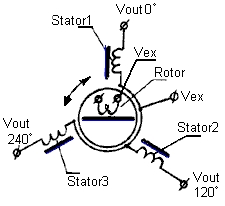
A synchro is, in effect, a transformer whose primary-to-secondary coupling may be varied by physically changing the relative orientation of the two windings. Synchros are often used for measuring the angle of a rotating machine such as an antenna platform or transmitting rotation. In its general physical construction, it is much like an electric motor. The primary winding of the transformer, fixed to the rotor, is excited by an alternating current, which by electromagnetic induction, causes voltages to appear between the Y-connected secondary windings fixed at 120 degrees to each other on the stator. The voltages are measured and used to determine the angle of the rotor relative to the stator.

A rotary variable differential transformer (RVDT) is a type of electrical transformer used for measuring angular displacement. The transformer has a rotor which can be turned by an external force. The transformer acts as an electromechanical transducer that outputs an alternating current (AC) voltage proportional to the angular displacement of its rotor shaft.

<span class="mw-page-title-main">Magnetic amplifier</span>

The magnetic amplifier is an electromagnetic device for amplifying electrical signals. The magnetic amplifier was invented early in the 20th century, and was used as an alternative to vacuum tube amplifiers where robustness and high current capacity were required. World War II Germany perfected this type of amplifier, and it was used in the V-2 rocket. The magnetic amplifier was most prominent in power control and low-frequency signal applications from 1947 to about 1957, when the transistor began to supplant it. The magnetic amplifier has now been largely superseded by the transistor-based amplifier, except in a few safety critical, high-reliability or extremely demanding applications. Combinations of transistor and mag-amp techniques are still used.

<span class="mw-page-title-main">Autotransformer</span> Type of electrical transformer

An autotransformer is an electrical transformer with only one winding. The "auto" prefix refers to the single coil acting alone, not to any kind of automatic mechanism. In an autotransformer, portions of the same winding act as both the primary winding and secondary winding sides of the transformer. In contrast, an ordinary transformer has separate primary and secondary windings which have metallic conducting path between them.

<span class="mw-page-title-main">Current transformer</span> Transformer used to scale alternating current, used as sensor for AC power

A current transformer (CT) is a type of transformer that is used to reduce or multiply an alternating current (AC). It produces a current in its secondary which is proportional to the current in its primary.

<span class="mw-page-title-main">Linear encoder</span>

A linear encoder is a sensor, transducer or readhead paired with a scale that encodes position. The sensor reads the scale in order to convert the encoded position into an analog or digital signal, which can then be decoded into position by a digital readout (DRO) or motion controller.

<span class="mw-page-title-main">Flyback converter</span> Type of voltage converter circuit

The flyback converter is used in both AC/DC, and DC/DC conversion with galvanic isolation between the input and any outputs. The flyback converter is a buck-boost converter with the inductor split to form a transformer, so that the voltage ratios are multiplied with an additional advantage of isolation. When driving, for example, a plasma lamp or a voltage multiplier, the rectifying diode of the boost converter is left out and the device is called a flyback transformer.

In electronics and signal processing, signal conditioning is the manipulation of an analog signal in such a way that it meets the requirements of the next stage for further processing.

A mechanical amplifier, or a mechanical amplifying element, is a linkage mechanism that amplifies the magnitude of mechanical quantities such as force, displacement, velocity, acceleration and torque in linear and rotational systems. In some applications, mechanical amplification induced by nature or unintentional oversights in man-made designs can be disastrous, causing situations such as the 1940 Tacoma Narrows Bridge collapse. When employed appropriately, it can help to magnify small mechanical signals for practical applications.

A variable reluctance sensor is a transducer that measures changes in magnetic reluctance. When combined with basic electronic circuitry, the sensor detects the change in presence or proximity of ferrous objects.

<span class="mw-page-title-main">Transformer types</span> Overview of electrical transformer types

A variety of types of electrical transformer are made for different purposes. Despite their design differences, the various types employ the same basic principle as discovered in 1831 by Michael Faraday, and share several key functional parts.

A position sensor is a sensor that detects an object's position. A position sensor may indicate the absolute position of the object or its relative position (displacement) in terms of linear travel, rotational angle or three-dimensional space. Common types of position sensors include the following:

<span class="mw-page-title-main">Current sensing</span>

In electrical engineering, current sensing is any one of several techniques used to measure electric current. The measurement of current ranges from picoamps to tens of thousands of amperes. The selection of a current sensing method depends on requirements such as magnitude, accuracy, bandwidth, robustness, cost, isolation or size. The current value may be directly displayed by an instrument, or converted to digital form for use by a monitoring or control system.

This glossary of electrical and electronics engineering is a list of definitions of terms and concepts related specifically to electrical engineering and electronics engineering. For terms related to engineering in general, see Glossary of engineering.

References

  1. "Borehole stress property measuring system".
  2. http://www.omega.com/manuals/manualpdf/M1120.pdf [ bare URL PDF ]
  3. 1 2 Baumeister & Marks 1967 , pp. 16–8
  4. Arun T Vemuri; Matthew Sullivan (2016). "Ratiometric measurements in the context of LVDT-sensor signal conditioning" (PDF). Texas Instruments Industrial Analog Applications Journal. Retrieved 27 October 2017.