Rotary encoder

Last updated
A Gray code absolute rotary encoder with 13 tracks. At the top, the housing, interrupter disk, and light source can be seen; at the bottom the sensing element and support components. Gray code rotary encoder 13-track opened.jpg
A Gray code absolute rotary encoder with 13 tracks. At the top, the housing, interrupter disk, and light source can be seen; at the bottom the sensing element and support components.

A rotary encoder, also called a shaft encoder, is an electro-mechanical device that converts the angular position or motion of a shaft or axle to analog or digital output signals. [1]

Contents

There are two main types of rotary encoder: absolute and incremental. The output of an absolute encoder indicates the current shaft position, making it an angle transducer. The output of an incremental encoder provides information about the motion of the shaft, which typically is processed elsewhere into information such as position, speed and distance.

Rotary encoders are used in a wide range of applications that require monitoring or control, or both, of mechanical systems, including industrial controls, robotics, photographic lenses, [2] computer input devices such as optomechanical mice and trackballs, controlled stress rheometers, and rotating radar platforms.

Technologies

Hall effect quadrature encoder, sensing gear teeth on the driveshaft of a robot vehicle. Odometergearcropped.jpg
Hall effect quadrature encoder, sensing gear teeth on the driveshaft of a robot vehicle.

Basic types

Absolute

An absolute encoder maintains position information when power is removed from the encoder. [5] The position of the encoder is available immediately on applying power. The relationship between the encoder value and the physical position of the controlled machinery is set at assembly; the system does not need to return to a calibration point to maintain position accuracy.

An absolute encoder has multiple code rings with various binary weightings which provide a data word representing the absolute position of the encoder within one revolution. This type of encoder is often referred to as a parallel absolute encoder. [6]

A multi-turn absolute rotary encoder includes additional code wheels and toothed wheels. A high-resolution wheel measures the fractional rotation, and lower-resolution geared code wheels record the number of whole revolutions of the shaft. [7]

Incremental

Incremental encoder Rotary encoder.jpg
Incremental encoder

An incremental encoder will immediately report changes in position, which is an essential capability in some applications. However, it does not report or keep track of absolute position. As a result, the mechanical system monitored by an incremental encoder may have to be homed (moved to a fixed reference point) to initialize absolute position measurements.

Absolute encoder

Absolute rotary encoder

Construction

Digital absolute encoders produce a unique digital code for each distinct angle of the shaft. They come in two basic types: optical and mechanical.

Mechanical absolute encoders

A metal disc containing a set of concentric rings of openings is fixed to an insulating disc, which is rigidly fixed to the shaft. A row of sliding contacts is fixed to a stationary object so that each contact wipes against the metal disc at a different distance from the shaft. As the disc rotates with the shaft, some of the contacts touch metal, while others fall in the gaps where the metal has been cut out. The metal sheet is connected to a source of electric current, and each contact is connected to a separate electrical sensor. The metal pattern is designed so that each possible position of the axle creates a unique binary code in which some of the contacts are connected to the current source (i.e. switched on) and others are not (i.e. switched off).

Brush-type contacts are susceptible to wear, and consequently mechanical encoders are typically found in low-speed applications such as manual volume or tuning controls in a radio receiver.

Optical absolute encoders

The optical encoder's disc is made of glass or plastic with transparent and opaque areas. A light source and photo detector array reads the optical pattern that results from the disc's position at any one time. [8] The Gray code is often used. This code can be read by a controlling device, such as a microprocessor or microcontroller to determine the angle of the shaft.

The absolute analog type produces a unique dual analog code that can be translated into an absolute angle of the shaft.

Magnetic absolute encoders

The magnetic encoder uses a series of magnetic poles (2 or more) to represent the encoder position to a magnetic sensor (typically magneto-resistive or Hall Effect). The magnetic sensor reads the magnetic pole positions.

This code can be read by a controlling device, such as a microprocessor or microcontroller to determine the angle of the shaft, similar to an optical encoder.

The absolute analog type produces a unique dual analog code that can be translated into an absolute angle of the shaft (by using a special algorithm[ citation needed ]).

Due to the nature of recording magnetic effects, these encoders may be optimal to use in conditions where other types of encoders may fail due to dust or debris accumulation. Magnetic encoders are also relatively insensitive to vibrations, minor misalignment, or shocks.

Brushless motor commutation

Built-in rotary encoders are used to indicate the angle of the motor shaft in permanent magnet brushless motors, which are commonly used on CNC machines, robots, and other industrial equipment. In such cases, the encoder serves as a feedback device that plays a vital role in proper equipment operation. Brushless motors require electronic commutation, which often is implemented in part by using rotor magnets as a low-resolution absolute encoder (typically six or twelve pulses per revolution). The resulting shaft angle information is conveyed to the servo drive to enable it to energize the proper stator winding at any moment in time.

Capacitive absolute encoders

An asymmetrical shaped disc is rotated within the encoder. This disc will change the capacitance between two electrodes which can be measured and calculated back to an angular value. [9]

Absolute multi-turn encoder

A multi-turn encoder can detect and store more than one revolution. The term absolute multi-turn encoder is generally used if the encoder will detect movements of its shaft even if the encoder is not provided with external power.

Battery-powered multi-turn encoder

This type of encoder uses a battery for retaining the counts across power cycles. It uses energy conserving electrical design to detect the movements.

Geared multi-turn encoder

These encoders use a train of gears to mechanically store the number of revolutions. The position of the single gears is detected with one of the above-mentioned technologies. [10]

Self-powered multi-turn encoder

These encoders use the principle of energy harvesting to generate energy from the moving shaft. This principle, introduced in 2007, [11] uses a Wiegand sensor to produce electricity sufficient to power the encoder and write the turns count to non-volatile memory. [12]

Ways of encoding shaft position

Standard binary encoding

Rotary encoder for angle-measuring devices marked in 3-bit binary. The inner ring corresponds to Contact 1 in the table. Black sectors are "on". Zero degrees is on the right-hand side, with angle increasing counterclockwise. Encoder disc (3-Bit binary).svg
Rotary encoder for angle-measuring devices marked in 3-bit binary. The inner ring corresponds to Contact 1 in the table. Black sectors are "on". Zero degrees is on the right-hand side, with angle increasing counterclockwise.

An example of a binary code, in an extremely simplified encoder with only three contacts, is shown below.

Standard Binary Encoding
SectorContact 1Contact 2Contact 3Angle
0offoffoff0° to 45°
1offoffON45° to 90°
2offONoff90° to 135°
3offONON135° to 180°
4ONoffoff180° to 225°
5ONoffON225° to 270°
6ONONoff270° to 315°
7ONONON315° to 360°

In general, where there are n contacts, the number of distinct positions of the shaft is 2n. In this example, n is 3, so there are 2³ or 8 positions.

In the above example, the contacts produce a standard binary count as the disc rotates. However, this has the drawback that if the disc stops between two adjacent sectors, or the contacts are not perfectly aligned, it can be impossible to determine the angle of the shaft. To illustrate this problem, consider what happens when the shaft angle changes from 179.9° to 180.1° (from sector 3 to sector 4). At some instant, according to the above table, the contact pattern changes from off-on-on to on-off-off. However, this is not what happens in reality. In a practical device, the contacts are never perfectly aligned, so each switches at a different moment. If contact 1 switches first, followed by contact 3 and then contact 2, for example, the actual sequence of codes is:

off-on-on (starting position)
on-on-on (first, contact 1 switches on)
on-on-off (next, contact 3 switches off)
on-off-off (finally, contact 2 switches off)

Now look at the sectors corresponding to these codes in the table. In order, they are 3, 7, 6 and then 4. So, from the sequence of codes produced, the shaft appears to have jumped from sector 3 to sector 7, then gone backwards to sector 6, then backwards again to sector 4, which is where we expected to find it. In many situations, this behaviour is undesirable and could cause the system to fail. For example, if the encoder were used in a robot arm, the controller would think that the arm was in the wrong position, and try to correct the error by turning it through 180°, perhaps causing damage to the arm.

Gray encoding

Rotary encoder for angle-measuring devices marked in 3-bit binary-reflected Gray code (BRGC). The inner ring corresponds to Contact 1 in the table. Black sectors are "on". Zero degrees is on the right-hand side, with angle increasing counter-clockwise. Encoder Disc (3-Bit).svg
Rotary encoder for angle-measuring devices marked in 3-bit binary-reflected Gray code (BRGC). The inner ring corresponds to Contact 1 in the table. Black sectors are "on". Zero degrees is on the right-hand side, with angle increasing counter-clockwise.

To avoid the above problem, Gray coding is used. This is a system of binary counting in which any two adjacent codes differ by only one bit position. For the three-contact example given above, the Gray-coded version would be as follows.

Gray Coding
SectorContact 1Contact 2Contact 3Angle
0offoffoff0° to 45°
1offoffON45° to 90°
2offONON90° to 135°
3offONoff135° to 180°
4ONONoff180° to 225°
5ONONON225° to 270°
6ONoffON270° to 315°
7ONoffoff315° to 360°

In this example, the transition from sector 3 to sector 4, like all other transitions, involves only one of the contacts changing its state from on to off or vice versa. This means that the sequence of incorrect codes shown in the previous illustration cannot happen.

Single-track Gray encoding

If the designer moves a contact to a different angular position (but at the same distance from the center shaft), then the corresponding "ring pattern" needs to be rotated the same angle to give the same output. If the most significant bit (the inner ring in Figure 1) is rotated enough, it exactly matches the next ring out. Since both rings are then identical, the inner ring can be omitted, and the sensor for that ring moved to the remaining, identical ring (but offset at that angle from the other sensor on that ring). Those two sensors on a single ring make a quadrature encoder with a single ring.

It is possible to arrange several sensors around a single track (ring) so that consecutive positions differ at only a single sensor; the result is the single-track Gray code encoder.

Data output methods

Depending on the device and manufacturer, an absolute encoder may use any of several signal types and communication protocols to transmit data, including parallel binary, analog signals (current or voltage), and serial bus systems such as SSI, BiSS, Heidenhain EnDat, Sick-Stegmann Hiperface, DeviceNet, Modbus, Profibus, CANopen and EtherCAT, which typically employ Ethernet or RS-422/RS-485 physical layers.

Incremental encoder

An incremental encoder ROD420 HEIDENHAIN.jpg
An incremental encoder
Two square waves in quadrature. The direction of rotation is indicated by the sign of the A-B phase angle which, in this case, is negative because A trails B. Quadrature Diagram.svg
Two square waves in quadrature. The direction of rotation is indicated by the sign of the A-B phase angle which, in this case, is negative because A trails B.
Conceptual drawing of a rotary incremental encoder sensor mechanism, with the corresponding logic states of the A and B signals Incremental directional encoder.gif
Conceptual drawing of a rotary incremental encoder sensor mechanism, with the corresponding logic states of the A and B signals

The rotary incremental encoder is the most widely used of all rotary encoders due to its ability to provide real-time position information. The measurement resolution of an incremental encoder is not limited in any way by its two internal, incremental movement sensors; one can find in the market incremental encoders with up to 10,000 counts per revolution, or more.

Rotary incremental encoders report position changes without being prompted to do so, and they convey this information at data rates which are orders of magnitude faster than those of most types of absolute shaft encoders. Because of this, incremental encoders are commonly used in applications that require precise measurement of position and velocity.

A rotary incremental encoder may use mechanical, optical or magnetic sensors to detect rotational position changes. The mechanical type is commonly employed as a manually operated "digital potentiometer" control on electronic equipment. For example, modern home and car stereos typically use mechanical rotary encoders as volume controls. Encoders with mechanical sensors require switch debouncing and consequently are limited in the rotational speeds they can handle. The optical type is used when higher speeds are encountered or a higher degree of precision is required.

A rotary incremental encoder has two output signals, A and B, which issue a periodic digital waveform in quadrature when the encoder shaft rotates. This is similar to sine encoders, which output sinusoidal waveforms in quadrature (i.e., sine and cosine), [13] thus combining the characteristics of an encoder and a resolver. The waveform frequency indicates the speed of shaft rotation and the number of pulses indicates the distance moved, whereas the A-B phase relationship indicates the direction of rotation.

Some rotary incremental encoders have an additional "index" output (typically labeled Z), which emits a pulse when the shaft passes through a particular angle. Once every rotation, the Z signal is asserted, typically always at the same angle, until the next AB state change. This is commonly used in radar systems and other applications that require a registration signal when the encoder shaft is located at a particular reference angle.

Unlike absolute encoders, an incremental encoder does not keep track of, nor do its outputs indicate the absolute position of the mechanical system to which it is attached. Consequently, to determine the absolute position at any particular moment, it is necessary to "track" the absolute position with an incremental encoder interface which typically includes a bidirectional electronic counter.

Inexpensive incremental encoders are used in mechanical computer mice. Typically, two encoders are used: one to sense left-right motion and another to sense forward-backward motion.

Rotary (Angle) Pulse Encoder

Rotary (Angle) Pulse Encoder Operation & Teardown Rotary Pulse Encoder Operation & Teardown.jpg
Rotary (Angle) Pulse Encoder Operation & Teardown

A Rotary (Angle) Pulse Encoder has a SPDT switch for each direction, with each one only operating in the direction of travel. Each turn indent in one direction causes the SPDT switch associated with that direction only to toggle.

Other pulse-output rotary encoders

Rotary encoders with a single output (i.e. tachometers) cannot be used to sense direction of motion but are suitable for measuring speed and for measuring position when the direction of travel is constant. In certain applications they may be used to measure distance of motion (e.g. feet of movement).

See also

Related Research Articles

<span class="mw-page-title-main">Potentiometer</span> Type of resistor, usually with three terminals

A potentiometer is a three-terminal resistor with a sliding or rotating contact that forms an adjustable voltage divider. If only two terminals are used, one end and the wiper, it acts as a variable resistor or rheostat.

<span class="mw-page-title-main">Hall effect sensor</span> Devices that measure magnetic field strength using the Hall effect

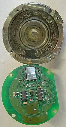
A Hall effect sensor is any sensor incorporating one or more Hall elements, each of which produce a voltage proportional to one axial component of the magnetic field vector B using the Hall effect.

<span class="mw-page-title-main">Contact breaker</span>

A contact breaker is a type of electrical switch, found in the ignition systems of spark-ignition internal combustion engines. The switch is automatically operated by a cam driven by the engine. The timing of operation of the switch is set so that a spark is produced at the right time to ignite the compressed air/fuel mixture in the cylinder of the engine. A mechanism may be provided to slightly adjust timing to allow for varying load on the engine. Since these contacts operate frequently, they are subject to wear, causing erratic ignition of the engine. More recent engines use electronic means to trigger the spark, which eliminated contact wear and allows computer control of ignition timing.

<span class="mw-page-title-main">Linear variable differential transformer</span> Type of electrical transformer

The linear variable differential transformer (LVDT) – also called linear variable displacement transformer, linear variable displacement transducer, or simply differential transformer – is a type of electrical transformer used for measuring linear displacement. A counterpart to this device that is used for measuring rotary displacement is called a rotary variable differential transformer (RVDT).

A resolver is a type of rotary electrical transformer used for measuring degrees of rotation. It is considered an analog device, and has digital counterparts such as the digital resolver, rotary encoder.

<span class="mw-page-title-main">Synchro</span> Variable transformers used in control systems

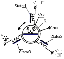
A synchro is, in effect, a transformer whose primary-to-secondary coupling may be varied by physically changing the relative orientation of the two windings. Synchros are often used for measuring the angle of a rotating machine such as an antenna platform or transmitting rotation. In its general physical construction, it is much like an electric motor. The primary winding of the transformer, fixed to the rotor, is excited by an alternating current, which by electromagnetic induction causes voltages to appear between the Y-connected secondary windings fixed at 120 degrees to each other on the stator. The voltages are measured and used to determine the angle of the rotor relative to the stator.

<span class="mw-page-title-main">Slip ring</span> Electromechanical device

A slip ring is an electromechanical device that allows the transmission of power and electrical signals from a stationary to a rotating structure. A slip ring can be used in any electromechanical system that requires rotation while transmitting power or signals. It can improve mechanical performance, simplify system operation and eliminate damage-prone wires dangling from movable joints.

In electrical engineering, a stepping switch or stepping relay, also known as a uniselector, is an electromechanical device that switches an input signal path to one of several possible output paths, directed by a train of electrical pulses.

<span class="mw-page-title-main">Paddle (game controller)</span> One-dimensional game controller

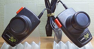
A paddle is a game controller with a round wheel and one or more fire buttons, where the wheel is typically used to control movement of the player object along one axis of the video screen. A paddle controller rotates through a fixed arc ; it has a stop at each end.

<span class="mw-page-title-main">Indicator (distance amplifying instrument)</span> Distance amplifying instrument

In various contexts of science, technology, and manufacturing, an indicator is any of various instruments used to accurately measure small distances and angles, and amplify them to make them more obvious. The name comes from the concept of indicating to the user that which their naked eye cannot discern; such as the presence, or exact quantity, of some small distance.

A wheel speed sensor (WSS) or vehicle speed sensor (VSS) is a type of tachometer. It is a sender device used for reading the speed of a vehicle's wheel rotation. It usually consists of a toothed ring and pickup.

<span class="mw-page-title-main">Servomotor</span> Type of motor

A servomotor is a rotary or linear actuator that allows for precise control of angular or linear position, velocity, and acceleration in a mechanical system. It constitutes part of a servomechanism, and consists of a suitable motor coupled to a sensor for position feedback. It also requires a relatively sophisticated controller, often a dedicated module designed specifically for use with servomotors.

<span class="mw-page-title-main">Linear encoder</span>

A linear encoder is a sensor, transducer or readhead paired with a scale that encodes position. The sensor reads the scale in order to convert the encoded position into an analog or digital signal, which can then be decoded into position by a digital readout (DRO) or motion controller.

<span class="mw-page-title-main">Optical chopper</span>

An optical chopper is a device which periodically interrupts a light beam. Three types are available: variable frequency rotating disc choppers, fixed frequency tuning fork choppers, and optical shutters. A rotating disc chopper was famously used in 1849 by Hippolyte Fizeau in the first non-astronomical measurement of the speed of light.

A detent is a mechanical or magnetic means to resist or arrest the movement of a mechanical device. Such a device can be anything ranging from a simple metal pin to a machine. The term is also used for the method involved.

A position sensor is a sensor that detects an object's position. A position sensor may indicate the absolute position of the object or its relative position (displacement) in terms of linear travel, rotational angle or three-dimensional space. Common types of position sensors include the following:

<span class="mw-page-title-main">Input device</span> Device that provides data and signals to a computer

In computing, an input device is a piece of equipment used to provide data and control signals to an information processing system, such as a computer or information appliance. Examples of input devices include keyboards, computer mice, scanners, cameras, joysticks, and microphones.

<span class="mw-page-title-main">Incremental encoder</span> Electromechanical device

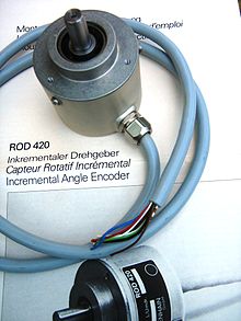
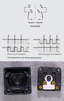
An incremental encoder is a linear or rotary electromechanical device that has two output signals, A and B, which issue pulses when the device is moved. Together, the A and B signals indicate both the occurrence of and direction of movement. Many incremental encoders have an additional output signal, typically designated index or Z, which indicates the encoder is located at a particular reference position. Also, some encoders provide a status output that indicates internal fault conditions such as a bearing failure or sensor malfunction.

<span class="mw-page-title-main">FRABA</span>

FRABA is a worldwide company founded in Germany. The company manufactures products for fabrication and process automation and is specialized in sensor manufacturing, for example sensors which are used in windmills and heavy machinery. The company holds several patents of encoder innovation. Until the 1960s, FRABA's main product was mechanical relays. In 1963 the company started selling brush rotary encoders, leading to the development of the first optical rotary encoder in 1973 and the magneticmulti-turnn rotary encoder in 2007.

In engineering, a solenoid is a device that converts electrical energy to mechanical energy, using an electromagnet formed from a coil of wire. The device creates a magnetic field from electric current, and uses the magnetic field to create linear motion. In electromagnetic technology, a solenoid is an actuator assembly with a sliding ferromagnetic plunger inside the coil. Without power, the plunger extends for part of its length outside the coil; applying power pulls the plunger into the coil. Electromagnets with fixed cores are not considered solenoids. In simple terms, a solenoid converts electrical energy into mechanical work. Typically, it has a multiturn coil of magnet wire surrounded by a frame, which is also a magnetic flux carrier to enhance its efficiency. In engineering, the term may also refer to a variety of transducer devices that convert energy into linear motion, more sophisticated than simple two–position actuators. The term "solenoid" also often refers to a solenoid valve, an integrated device containing an electromechanical solenoid which actuates either a pneumatic or hydraulic valve, or a solenoid switch, which is a specific type of relay that internally uses an electromechanical solenoid to operate an electrical switch; for example, an automobile starter solenoid or linear solenoid. Solenoid bolts, a type of electromechanical locking mechanism, also exist.

References

  1. Murray, Mike (15 December 2019). "How Rotary Encoders Work". The Geek Pub. Retrieved 3 September 2019.
  2. "New - Rotary Encoder". Archived from the original on 2013-10-05. Canon video camera lens, used for zoom and aperture control
  3. "A Designer's Guide to Encoders". digikey.com. 19 April 2012. Retrieved 23 November 2019.
  4. "MassMind Magnetic High Speed Non-Contact Quadrature Encoder V2". MassMind.org. 10 January 2018. Retrieved 12 July 2019.
  5. Eitel, Elisabeth. Basics of rotary encoders: Overview and new technologies | Machine Design Magazine, 7 May 2014. Accessed: 30 June 2014
  6. TI-5000EX Serial/Incremental Encoder Test System User Manual [ permanent dead link ], Mitchell Electronics, Inc.
  7. G. K. McMillan, D.M. Considine (ed.) Process Instruments and Controls Handbook Fifth Edition, McGraw Hill 1999, ISBN   978-0-07-012582-7, page 5.26
  8. "encoders" (PDF). p. 12. Retrieved 20 February 2013.
  9. "Capacitive Absolute Encoder" (PDF). Camille Bauer. Retrieved 20 February 2013.
  10. Robert, Repas. "Multi-turn absolute encoders". machinedesign.com. Retrieved 20 February 2013.[ permanent dead link ]
  11. "New technology yields encoder that never forgets". journal. www.motioncontrol.co.za. 2007. Retrieved 20 February 2013.
  12. "White Paper Magnetic Encoder" (PDF). FRABA Inc. p. 3. Retrieved 13 February 2013.
  13. Collins, Danielle. "What is a sine encoder (aka sine-cosine encoder)?". Design World. Retrieved 19 August 2020.

Further reading