The word traction from Latin, being the agent noun of trahere "to pull" in the sense of "drawn"[1][2][3] was used for the naming of traction engines developed circa 1870.[4]
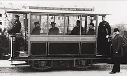
The first experimental electric traction motor tramway of 1875 was rapidly developed internationally for city use.[5][6][7] In the 19th century traction motor passenger car companies began to compete with the dominant citywide horse-drawn railway transportation system.[8][9][10]
Motor types and control
Direct-current motors with series field windings are the oldest type of traction motors. These provide a speed-torque characteristic useful for propulsion, providing high torque at lower speeds for the acceleration of the vehicle, and declining torque as speed increases. By arranging the field winding with multiple taps, the speed characteristic can be varied, allowing relatively smooth operator control of acceleration. A further measure of control is provided by using pairs of motors on a vehicle in series-parallel control; for slow operation or heavy loads, two motors can be run in a series of the direct-current supply. Where higher speed is desired, these motors can be operated in parallel, making a higher voltage available at each motor and so allowing higher speeds. Parts of a rail system might use different voltages, with higher voltages in long runs between stations and lower voltages near stations where only slower operation is needed.
A variant of the DC system is the AC series motor, also known as the universal motor, which is essentially the same device but operates on alternating current. Since both the armature and field current reverse at the same time, the behavior of the motor is similar to that when energized with direct current. To achieve better operating conditions, AC railways are often supplied with current at a lower frequency than the commercial supply used for general lighting and power; special traction current power stations are used, or rotary converters used to convert 50 or 60Hz commercial power to the 25Hz or 16+2⁄3Hz frequency used for AC traction motors. Because it permits the simple use of transformers, the AC system allows efficient distribution of power down the length of a rail line, and also permits speed control with switchgear on the vehicle.
AC induction motors and synchronous motors are simple and low maintenance, but up until the advent of power semiconductors, were awkward to apply for traction motors because of their fixed speed characteristic. An AC induction motor generates useful amounts of power only over a narrow speed range determined by its construction and the frequency of the AC power supply. The advent of power semiconductors has made it possible to fit a variable frequency drive on a locomotive; this allows a wide range of speeds, AC power transmission, and the use of rugged induction motors that do not have wearing parts like brushes and commutators.[11]
Traditionally road vehicles (cars, buses, and trucks) have used diesel and petrol engines with a mechanical or hydraulic transmission system. In the latter part of the 20th century, vehicles with electrical transmission systems (powered by internal combustion engines, batteries, or fuel cells) began to be developed—one advantage of using electric machines is that specific types can regenerate energy (i.e. act as a regenerative brake)—providing deceleration as well as increasing overall efficiency by charging the battery pack.
Railways
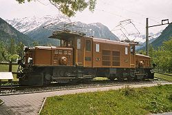
Swiss Rhaetian Railway Ge 6/6 IKrokodil locomotive, with a single large traction motor above each bogie, with drive by coupling rods
Traditionally, these were series-wound brushed DC motors, usually running on approximately 600 volts. The availability of high-powered semiconductors (thyristors and the IGBT) has now made practical the use of much simpler, higher-reliability ACinduction motors known as asynchronous traction motors. Synchronous AC motors are also occasionally used, as in the French TGV.
Nose-suspended DC traction motor for a Czech ČD class 182 locomotive
Usually, the traction motor is three-point suspended between the bogie frame and the driven axle; this is referred to as a "nose-suspended traction motor". The problem with such an arrangement is that a portion of the motor's weight is unsprung, increasing unwanted forces on the track. In the case of the famous Pennsylvania Railroad GG1, two frame-mounted motors drove each axle through a quill drive. The "Bi-Polar" electric locomotives built by General Electric for the Milwaukee Road had direct drive motors. The rotating shaft of the motor was also the axle for the wheels. In the case of French TGV power cars, a motor mounted to the power car's frame drives each axle; a "tripod" drive allows a small amount of flexibility in the drive train allowing the trucks bogies to pivot. By mounting the relatively heavy traction motor directly to the power car's frame, rather than to the bogie, better dynamics are obtained, allowing better high-speed operation.[12]
Rating
Electric locomotives usually have a continuous and one-hour rating. The one-hour rating is the maximum power that the motors can continuously develop over one hour without overheating. Such a test starts with the motors at +25°C (and the outside air used for ventilation also at +25°C). In the USSR, per GOST 2582-72 with class N insulation, the maximum temperatures allowed for DC motors were 160°C for the armature, 180°C for the stator, and 105°C for the collector.[13] The one-hour rating is typically about 10% higher than the continuous rating and is limited by the temperature rise in the motor.
As traction motors use a reduction gear setup to transfer torque from the motor armature to the driven axle, the actual load placed on the motor varies with the gear ratio. Otherwise "identical" traction motors can have significantly different load rating. A traction motor geared for freight use with a low gear ratio will safely produce higher torque at the wheels for a longer period at the same current level because the lower gears give the motor more mechanical advantage.
Individual traction motor ratings usually range up 1,600kW (2,100hp).
Another important factor when traction motors are designed or specified is operational speed. The motor armature has a maximum safe rotating speed at or below which the windings will stay safely in place.
Above this maximum speed centrifugal force on the armature will cause the windings to be thrown outward. In severe cases, this can lead to "birdnesting" as the windings contact the motor housing and eventually break loose from the armature entirely and uncoil.
Bird-nesting (the centrifugal ejection of the armature's windings) due to overspeed can occur either in operating traction motors of powered locomotives or in traction motors of dead-in-consist locomotives being transported within a train traveling too fast. Another cause is replacement of worn or damaged traction motors with units incorrectly geared for the application.
Damage from overloading and overheating can also cause bird-nesting below rated speeds when the armature assembly and winding supports and retainers have been damaged by the previous abuse.
Cooling
Because of the high power levels involved, traction motors are almost always cooled using forced air, water or a special dielectric liquid.
Typical cooling systems on U.S. diesel-electric locomotives consist of an electrically powered fan blowing air into a passage integrated into the locomotive frame. Rubber cooling ducts connect the passage to the individual traction motors and cooling air travels down and across the armatures before being exhausted to the atmosphere.
↑ Merriam-Webster Unabridged (MWU). (Online subscription-based reference service of Merriam-Webster, based on Webster's Third New International Dictionary, Unabridged. Merriam-Webster, 2002.) Headword tractor. Accessed 2007-09-22.
↑ Haupt, Herman (1893). Street railway motors. H.C. Baird & Company. The subjects here considered are horse railroads steam motors cable traction electric roads com pressed air motors ammonia motors hot water motors gas motors and carbonic acid motors
↑ Andreas Steimel Electric Traction - Motive Power and Energy Supply: Basics and Practical Experience Oldenbourg Industrieverlag, 2008 ISBN3835631322; Chapter 6 "Induction Traction Motors and Their Control"
Image of a nose mounted traction motor on an R46 New York City Subway car. The motor can be clearly seen behind the axle with the gear box with the writing on it in the center.
This page is based on this Wikipedia article Text is available under the CC BY-SA 4.0 license; additional terms may apply. Images, videos and audio are available under their respective licenses.