1909 500kW Westinghouse rotary converterA rotary converter plant in Germany where three phase AC of 50 hertz is transformed into single phase AC of 16.67 hertz for the traction current networkAC to DC plant in Baltimore, Maryland, 1910
A rotary converter is a type of electrical machine which acts as a mechanical rectifier, inverter or frequency converter. Rotary converters were used to convert alternating current (AC) to direct current (DC), or DC to AC power, before the advent of chemical or solid state power rectification and inverting. They were commonly used to provide DC power for commercial, industrial and railway electrification from an AC power source.[1]
A rotary converter plant is a facility at which rotary converters are used. With appropriate equipment, such facilities may also allow the setting of voltages and frequencies. Rotary converter plants were commonplace in railway electrification before the invention of mercury arc rectifiers in the 1920s. At each facility, power from an AC power grid was converted to DC to feed into an overhead line or a third rail of a railway. Rotary converter plants were also used for coupling power grids of different frequencies and operation modes. The former Neuhof Substation was an example of the latter. Former machinery transmitters like the Alexanderson alternator were, strictly speaking, rotary converter plants. In spite of modern power semiconductor technology, rotary converters are still common for feeding railway systems with AC of a different frequency from that of the main electricity grid. In Europe, this would typically be for 15 kV AC railway electrification.
Principles of operation
Wiring schematic for a simplified bipolar-fieldGramme-ringsingle-phase–to–direct-current rotary converter. (In actual use, the converter is drum-wound and uses a multipolar field.)Wiring schematic for a simplified two-phase–to–direct-current rotary converter, with the second phase connected at right angles to the firstWiring schematic for a simplified three-phase–to–direct-current rotary converter, with the phases separated by 120 degrees on the commutator
The rotary converter can be thought of as a motor–generator, where the two machines share a single rotating armature and set of field coils. The basic construction of the rotary converter consists of a DC generator (dynamo) with a set of slip rings tapped into its rotor windings at evenly spaced intervals. When a dynamo is spun the electric currents in its rotor windings alternate as it rotates in the magnetic field of the stationary field windings. This alternating current is rectified by means of a commutator, which allows direct current to be extracted from the rotor. This principle is taken advantage of by energizing the same rotor windings with AC power, which causes the machine to act as a synchronous AC motor. The rotation of the energized coils excites the stationary field windings producing part of the direct current. The other part is alternating current from the slip rings, which is directly rectified into DC by the commutator. This makes the rotary converter a hybrid dynamo and mechanical rectifier. When used in this way it is referred to as a synchronous rotary converter or simply a synchronous converter. The AC slip rings also allow the machine to act as an alternator.
The device can be reversed and DC applied to the field and commutator windings to spin the machine and produce AC power. When operated as a DC to AC machine it is referred to as an inverted rotary converter.
One way to envision what is happening in an AC-to-DC rotary converter is to imagine a rotary reversing switch that is being driven at a speed that is synchronous with the power line. Such a switch could rectify the AC input waveform with no magnetic components at all save those driving the switch. The rotary converter is somewhat more complex than this trivial case because it delivers near-DC rather than the pulsating DC that would result from just the reversing switch, but the analogy may be helpful in understanding how the rotary converter avoids transforming all of the energy from electrical to mechanical and back to electrical.
Simplistically put, when one motor is powered, the opposing motor receives the mechanical energy, which causes it to generate current in the opposite form. Depending on which side is powered, the device converts AC to DC or DC to AC.
The advantage of the rotary converter over the discrete motor–generator set is that the rotary converter avoids converting all of the power flow into mechanical energy and then back into electrical energy; some of the electrical energy instead flows directly from input to output, allowing the rotary converter to be much smaller and lighter than a motor–generator set of an equivalent power-handling capability. The advantages of a motor–generator set include adjustable voltage regulation, which can compensate for voltage drop in the supply network; it also provided complete power isolation, harmonics isolation, greater surge and transient protection, and sag (brownout) protection through increased momentum.
In this first illustration of a single-phase to direct-current rotary converter, it may be used five different ways:[5]
If the coil is rotated, alternating currents can be taken from the collector rings, and it is called an alternator.
if the coil is rotated, direct current can be taken from the commutator, and it is called a dynamo.
If the coil is rotated, two separate currents can be taken from the armature, one providing direct current and the other providing alternating current. Such a machine is called a double current generator.
If a direct current is applied to the commutator, the coil will begin to rotate as a commutated electric motor and an alternating current can be taken out of the collector rings. This is called an inverted rotary converter (see inverter).
If the machine is brought up to synchronous speed by external means and if the direction of the current through the armature has the correct relationship to the field coils, then the coil will continue to rotate in synchronism with the alternating current as a synchronous motor. A direct current can be taken from the commutator. When used this way, it is called a rotary converter.
The self-balancing dynamo is of similar construction to the single- and two-phase rotary converter. It was commonly used to create a completely balanced three-wire 120/240-volt AC electrical supply. The AC extracted from the slip rings was fed into a transformer with a single center-tapped winding. The center-tapped winding forms the DC neutral wire. It needed to be driven by a mechanical power source, such as a steam engine, diesel engine, or electric motor. It could be considered a rotary converter used as a double current generator; the alternating current was used to balance the DC neutral wire.
Rotary phase converter
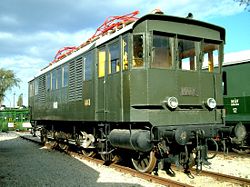
A simple homemade phase converterThe first locomotive with a phase converter (only for demonstration purposes)The Kandó phase converter (1933)The "Kandó" locomotive, the first locomotive using a phase converter system
A rotary phase converter, abbreviated RPC, is an electrical machine that converts power from one polyphase system to another, converting through rotary motion. Typically, single-phase electric power is used to produce three-phase electric power locally to run three-phase loads in premises where only single-phase is available. It may be built as a motor–generator set. These completely isolate the load from the single-phase supply and produce balanced three-phase output. However, due to weight, cost, and efficiency concerns, most RPCs are not built this way.
Instead, they are built out of a three-phase induction motor or generator, called an idler, on which two of the terminals (the idler inputs) are powered from the single-phase line. The rotating flux in the motor produces a voltage on the third terminal. A voltage is induced in the third terminal that is phase shifted from the voltage between the first two terminals. In a three-winding motor, two of the windings are acting as a motor, and the third winding is acting as a generator. Since the third, synthesized phase is driven differently from the other two, its response to load changes may be different causing this phase to sag more under load. Since induction motors are sensitive to voltage imbalance, this is another factor in de-rating of motors driven by this type of phase converter. For example, a small 5% imbalance in phase voltage requires a much larger 24% reduction of motor rated power.[6] Thus tuning a rotary phase converter circuit for equal phase voltages under maximum load may be quite important.
Rotary phase converters are used to produce a single-phase for the single overhead conductor in electric railways.[citation needed] Five European countries (Germany, Austria, Switzerland, Norway, and Sweden), where electricity is three-phase AC at 50Hz, have standardised on single-phase AC at 15kV16+2⁄3Hz for railway electrification; phase converters are, therefore, used to change both phases and frequency. In the Soviet Union, they were used on AC locomotives to convert single-phase, 50Hz to three-phase for driving induction motors for traction motor cooling blowers, etc.[7]
The rotary converter was invented by Charles S. Bradley in 1888.[8] A typical use for this type of AC/DC converter was for railway electrification, where utility power was supplied as alternating current. Trains were designed to work on direct current, since DC traction motors could be built with speed and torque characteristics suited to propulsion use, and could be controlled for variable speed. The AC induction motor was not as well suited to traction use when powered from a fixed frequency supply. Before the invention of mercury-arc rectifiers and high-power semiconductorrectifiers, this conversion could only be accomplished using motor–generators or rotary converters.
Rotary converters soon filled the need to use all the competing electric power delivery systems that cropped up in the 1880s and early 1890s. These included single phase AC systems, poly-phase AC systems, low voltage incandescent lighting, high voltage arc lighting, and existing DC motors in factories and street cars.[9][10] Most machinery and appliances at that time were operated by DC power, which was provided at the user level by rotary converter substations for residential, commercial and industrial consumption. Rotary converters provided high current DC power for industrial electrochemical processes such as electroplating. Steel mills needed large amounts of on-site DC power for their main roll drive motors. Similarly, paper mills and printing presses required direct current to start and stop their motors in perfect synchronization to prevent tearing the sheet.
Obsolescence
The need for rotary converters was slowly overcome, as older systems were retired or upgraded to match the newer AC universal system. AC to DC synchronous rotary converters were made obsolete by mercury arc rectifiers in the 1930s and later by semiconductor rectifiers in the 1960s.[11]:54 Some of the original New York City Subway substations using synchronous rotary converters operated until 1999.[11]:12
Compared to the rotary converter, the new mercury arc and semiconductor rectifiers did not need daily maintenance, manual synchronizing for parallel operation, nor skilled personnel, and they provided clean DC power. This enabled the new substations to be unmanned, only requiring periodic visits from a technician for inspection and maintenance.
AC replaced DC in most applications and eventually the need for local DC substations diminished along with the need for rotary converters. Many DC customers converted to AC power, and on-site solid-state DC rectifiers were used to power the remaining DC equipment from the AC supply.
↑Hughes, Thomas Parke. Networks of Power: Electrification in Western Society, 1880–1930. Baltimore, Maryland: Johns Hopkins University Press - 1993, pp=120–121
↑Garud, Raghu; Kumaraswamy, Arun; Langlois, Richard (2009). Managing in the Modular Age: Architectures, Networks, and Organizations. New York: John Wiley & Sons. p. 249
↑Hughes, Thomas Parke. Networks of Power: Electrification in Western Society, 1880–1930. Baltimore, Maryland: Johns Hopkins University Press - 1993, pp=120–121
12Payne, Christopher (2002). New York's Forgotten Substations: The Power Behind the Subway. Princeton Architectural Press. ISBN978-1568983554.
Slichter, W.I. (1917). "Converters, Synchronous or Rotary". In Pender, Harold (ed.). Handbook for Electrical Engineers. New York: John Wiley & Sons. pp.279–291.
This page is based on this Wikipedia article Text is available under the CC BY-SA 4.0 license; additional terms may apply. Images, videos and audio are available under their respective licenses.