A locomotive is a rail transport vehicle that provides the motive power for a train. If a locomotive is capable of carrying a payload, it is usually rather referred to as a multiple unit, motor coach, railcar or power car; the use of these self-propelled vehicles is increasingly common for passenger trains, but rare for freight trains.

An electric locomotive is a locomotive powered by electricity from overhead lines, a third rail or on-board energy storage such as a battery or a supercapacitor. Locomotives with on-board fuelled prime movers, such as diesel engines or gas turbines, are classed as diesel–electric or gas turbine–electric and not as electric locomotives, because the electric generator/motor combination serves only as a power transmission system.

Railway electrification is the use of electric power for the propulsion of rail transport. Electric railways use either electric locomotives, electric multiple units or both. Electricity is typically generated in large and relatively efficient generating stations, transmitted to the railway network and distributed to the trains. Some electric railways have their own dedicated generating stations and transmission lines, but most purchase power from an electric utility. The railway usually provides its own distribution lines, switches, and transformers.

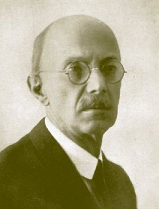
Kálmán Kandó de Egerfarmos et Sztregova was a Hungarian engineer, the inventor of phase converter and a pioneer in the development of AC electric railway traction.

Railway electrification systems using alternating current (AC) at 25 kilovolts (kV) are used worldwide, especially for high-speed rail. It is usually supplied at the standard utility frequency, which simplifies traction substations. The development of 25 kV AC electrification is closely connected with that of successfully using utility frequency.

Railway electrification using alternating current (AC) at 15 kilovolts (kV) and 16.7 hertz (Hz) are used on transport railways in Germany, Austria, Switzerland, Sweden, and Norway. The high voltage enables high power transmission with the lower frequency reducing the losses of the traction motors that were available at the beginning of the 20th century. Globally, railway electrification in late 20th century tends to use 25 kV, 50 Hz AC systems which has become the preferred standard for new railway electrifications. Nevertheless, local extensions of the existing 15 kV network is commonplace. In particular, the Gotthard Base Tunnel uses 15 kV, 16.7 Hz electrification.
Railroad electrification in the United States began at the turn of the 20th century and comprised many different systems in many different geographical areas, few of which were connected. Despite this situation, these systems shared a small number of common reasons for electrification.
Railway electric traction describes the various types of locomotive and multiple units that are used on electrification systems around the world.

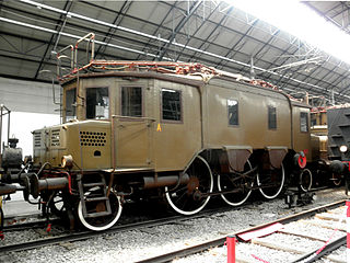
The FS Class E.550 was a class of three-phase electric locomotive used in Italy, introduced in the 20th century, which remained in service until 1965.

The FS Class E.330 was a small class of three-phase electric locomotive used in Italy, introduced in the 1910s.

The New York, New Haven and Hartford Railroad pioneered electrification of main line railroads using high-voltage, alternating current, single-phase overhead catenary. It electrified its mainline between Stamford, Connecticut, and Woodlawn, New York, in 1907 and extended the electrification to New Haven, Connecticut, in 1914. While single-phase AC railroad electrification has become commonplace, the New Haven's system was unprecedented at the time of construction. The significance of this electrification was recognized in 1982 by its designation as a Historic Mechanical Engineering Landmark by the American Society of Mechanical Engineers (ASME).

Baldwin, the locomotive manufacturer, and Westinghouse, the promoter of AC electrification, joined forces in 1895 to develop AC railway electrification. Soon after the turn of the century, they marketed a single-phase high-voltage system to railroads. From 1904 to 1905 they supplied locomotives carrying a joint builder's plate to a number of American railroads, particularly for the New Haven line from New York to New Haven, and other New Haven lines. Westinghouse would produce the motors, controls, and other electrical gear, while Baldwin would produce the running gear, frame, body, and perform final assembly.

The Seebach-Wettingen railway electrification trial (1905-1909) was an important milestone in the development of electric railways. Maschinenfabrik Oerlikon (MFO) demonstrated the suitability of single-phase alternating current at high voltage for long-distance railway operation with the Seebach-Wettingen single-phase alternating current test facility. For this purpose, MFO electrified the 19.45-kilometre-long Swiss Federal Railways (SBB) route from Seebach to Wettingen at its own expense with single-phase alternating current at 15,000 volts.

The FS Class E.360 were electric locomotives of the Italian State Railways (FS), using three-phase alternating current, built for the operation of the Valtellina line. They were ordered by Rete Adriatica and were originally numbered RA 361–363. Italian railways were nationalized in 1905 and they then became FS E.361-363 They were leased to Swiss Federal Railways (SBB) in 1906 and returned to Italy in 1907.
The FS Class E.470 was an electric locomotive class of the state-owned Italian railway Ferrovie dello Stato. It was used on the Italian three-phase test line from Rome-Sulmona especially in express train service. After the end of the trial operation in 1945, the locomotives were scrapped, and no locomotive of the class has been preserved.

The Ferrovia della Valtellina is a railway line in Italy that runs from Lecco to Valtellina and Valchiavenna. It was opened in 1894 and electrified on the three-phase system in 1902. It is now electrified at 3 kV direct current and operated by Trenord.

The FS Class E.430 locomotives, initially classed as RA 34, were three-phase alternating current electric locomotives of the Italian railways. They were built for Ferrovia della Valtellina by Ganz and MÁVAG in 1901 and had a power output of 440 kW and a haulage capacity of 300 tons. One locomotive is preserved.

The Great Northern Z-1 was a class of ten electric locomotives built for the Great Northern Railway They were used to work the route through the second Cascade Tunnel. They were built between 1926–1928 by Baldwin Locomotive Works, with Westinghouse electrics, and stayed in service until dieselisation in 1956. Each was of 1,830 horsepower (1,360 kW) with a 1-D-1 wheel arrangement, although they were always used in coupled pairs.

Rigid-framed electric locomotives were some of the first generations of electric locomotive design. When these began the traction motors of these early locomotives, particularly with AC motors, were too large and heavy to be mounted directly to the axles and so were carried on the frame. One of the initial simplest wheel arrangements for a mainline electric locomotive, from around 1900, was the 1′C1′ arrangement, in UIC classification.

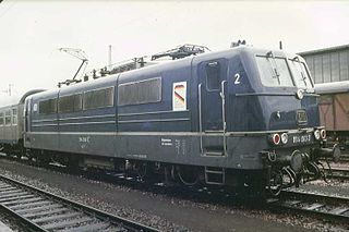
The DB Class E 410 locomotive of the German Federal Railroad (DB), also known as DB Class 184, was one of the first four-current electric locomotives provided for international services from Germany to France, Belgium, Luxembourg and the Netherlands.


