Workings of a brushed electric motor with a two-pole rotor (armature) and permanent magnet stator. "N" and "S" designate polarities on the inside axis faces of the magnets; the outside faces have opposite polarities. The + and - signs show where the DC current is applied to the commutator which supplies current to the armature coils
The Pennsylvania Railroad's class DD1 locomotive running gear was a semi-permanently coupled pairing of third rail direct current electric locomotive motors built for the railroad's initial New York-area electrification when steam locomotives were banned in the city (locomotive cab removed here).
A DC motor is an electrical motor that uses direct current (DC) to produce mechanical force. The most common types rely on magnetic forces produced by currents in the coils. Nearly all types of DC motors have some internal mechanism, either electromechanical or electronic, to periodically change the direction of current in part of the motor.
DC motors were the first form of motors to be widely used, as they could be powered from existing direct-current lighting power distribution systems. A DC motor's speed can be controlled over a wide range, using either a variable supply voltage or by changing the strength of current in its field windings. Small DC motors are used in tools, toys, and appliances. The universal motor, a lightweight brushed motor used for portable power tools and appliances can operate on direct current and alternating current. Larger DC motors are currently used in propulsion of electric vehicles, elevator and hoists, and in drives for steel rolling mills. The advent of power electronics has made replacement of DC motors with AC motors possible in many applications.
Electromagnetic motors
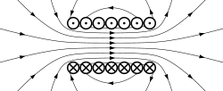
A coil of wire with a current running through it generates an electromagnetic field aligned with the center of the coil. The direction and magnitude of the magnetic field produced by the coil can be changed with the direction and magnitude of the current flowing through it.
A simple DC motor has a stationary set of magnets in the stator and an armature with one or more windings of insulated wire wrapped around a soft iron core that concentrates the magnetic field. The windings usually have multiple turns around the core, and in large motors there can be several parallel current paths. The ends of the wire winding are connected to a commutator. The commutator allows each armature coil to be energized in turn and connects the rotating coils with the external power supply through brushes. (Brushless DC motors have electronics that switch the DC current to each coil on and off and have no brushes.)
The total amount of current sent to the coil, the coil's size, and what it is wrapped around decide the strength of the electromagnetic field created.
The sequence of turning a particular coil on or off dictates what direction the effective electromagnetic fields are pointed. By turning on and off coils in sequence, a rotating magnetic field can be created. These rotating magnetic fields interact with the magnetic fields of the magnets (permanent or electromagnets) in the stationary part of the motor (stator) to create a torque on the armature which causes it to rotate. In some DC motor designs, the stator fields use electromagnets to create their magnetic fields which allows greater control over the motor.
At high power levels, DC motors are almost always cooled using forced air.
Different number of stator and armature fields as well as how they are connected provide different inherent speed and torque regulation characteristics. The speed of a DC motor can be controlled by changing the voltage applied to the armature. Variable resistance in the armature circuit or field circuit allows speed control. Modern DC motors are often controlled by power electronics systems which adjust the voltage by "chopping" the DC current into on and off cycles which have an effective lower voltage.
Since the series-wound DC motor develops its highest torque at low speed, it is often used in traction applications such as electric locomotives, and trams. The introduction of DC motors and an electrical grid system to run machinery starting in the 1870s started a new second Industrial Revolution. DC motors can operate directly from rechargeable batteries, providing the motive power for the first electric vehicles and today's hybrid cars and electric cars as well as driving a host of cordless tools. Today DC motors are still found in applications as small as toys and disk drives, or in large sizes to operate steel rolling mills and paper machines. Large DC motors with separately excited fields were generally used with winder drives for mine hoists, for high torque as well as smooth speed control using thyristor drives. These are now replaced with large AC motors with variable frequency drives.
If external mechanical power is applied to a DC motor it acts as a DC generator, a dynamo. This feature is used to slow down and recharge batteries on hybrid and electric cars or to return electricity back to the electric grid used on a street car or electric powered train line when they slow down. This process is called regenerative braking on hybrid and electric cars. In diesel electric locomotives they also use their DC motors as generators to slow down but dissipate the energy in resistor stacks. Newer designs are adding large battery packs to recapture some of this energy.
A brushed DC electric motor generating torque from DC power supply by using an internal mechanical commutation. Stationary permanent magnets form the stator field. Torque is produced by the principle that any current-carrying conductor placed within an external magnetic field experiences a force, known as Lorentz force. In a motor, the magnitude of this Lorentz force (a vector represented by the green arrow), and thus the output torque, is a function for rotor angle, leading to a phenomenon known as torque ripple. Since this is a two-pole motor, the commutator consists of a split ring, so that the current reverses each half turn (180 degrees).
The brushed DC electric motor generates torque directly from DC power supplied to the motor by using internal commutation, stationary magnets (permanent or electromagnets), and rotating electromagnets.
Advantages of a brushed DC motor include low initial cost, high reliability, and simple control of motor speed. Disadvantages are high maintenance and low life-span for high intensity uses. Maintenance involves regularly replacing the carbon brushes and springs which carry the electric current, as well as cleaning or replacing the commutator. These components are necessary for transferring electrical power from outside the motor to the spinning wire windings of the rotor inside the motor.
Brushes are usually made of graphite or carbon, sometimes with added dispersed copper to improve conductivity. In use, the soft brush material wears to fit the diameter of the commutator, and continues to wear. A brush holder has a spring to maintain pressure on the brush as it shortens. For brushes intended to carry more than an ampere or two, a flying lead will be molded into the brush and connected to the motor terminals. Very small brushes may rely on sliding contact with a metal brush holder to carry current into the brush, or may rely on a contact spring pressing on the end of the brush. The brushes in very small, short-lived motors, such as are used in toys, may be made of a folded strip of metal that contacts the commutator.
Typical brushless DC motors use one or more permanent magnets in the rotor and electromagnets on the motor housing for the stator. A motor controller converts DC to AC. This design is mechanically simpler than that of brushed motors because it eliminates the complication of transferring power from outside the motor to the spinning rotor. The motor controller can sense the rotor's position via Hall effect sensors or similar devices and can precisely control the timing, phase, etc., of the current in the rotor coils to optimize torque, conserve power, regulate speed, and even apply some braking. Advantages of brushless motors include long life span, little or no maintenance, and high efficiency. Disadvantages include high initial cost, and more complicated motor speed controllers. Some such brushless motors are sometimes referred to as "synchronous motors" although they have no external power supply to be synchronized with, as would be the case with normal AC synchronous motors.
Uncommutated
Other types of DC motors require no commutation.
Homopolar motor – A homopolar motor has a magnetic field along the axis of rotation and an electric current that at some point is not parallel to the magnetic field. The name homopolar refers to the absence of polarity change. Homopolar motors necessarily have a single-turn coil, which limits them to very low voltages. This has restricted the practical application of this type of motor.
Ball bearing motor – A ball bearing motor is an unusual electric motor that consists of two ball bearing-type bearings, with the inner races mounted on a common conductive shaft, and the outer races connected to a high current, low voltage power supply. An alternative construction fits the outer races inside a metal tube, while the inner races are mounted on a shaft with a non-conductive section (e.g. two sleeves on an insulating rod). This method has the advantage that the tube will act as a flywheel. The direction of rotation is determined by the initial spin which is usually required to get it going.
A permanent magnet (PM) motor does not have a field winding on the stator frame, instead relying on PMs to provide the magnetic field against which the rotor field interacts to produce torque. Compensation windings in series with the armature may be used on large motors to improve commutation under load. Because this field is fixed, it cannot be adjusted for speed control. PM fields (stators) are convenient in miniature motors to eliminate the power consumption of the field winding. Most larger DC motors are of the "dynamo" type, which have stator windings. Historically, PMs could not be made to retain high flux if they were disassembled; field windings were more practical to obtain the needed amount of flux. However, large PMs are costly, as well as dangerous and difficult to assemble; this favors wound fields for large machines.
To minimize overall weight and size, miniature PM motors may use high energy magnets made with neodymium or other strategic elements; most such are neodymium-iron-boron alloy. With their higher flux density, electric machines with high-energy PMs are at least competitive with all optimally designed singly fed synchronous and induction electric machines. Miniature motors resemble the structure in the illustration, except that they have at least three rotor poles (to ensure starting, regardless of rotor position) and their outer housing is a steel tube that magnetically links the exteriors of the curved field magnets.
Wound stators
A field coil may be connected in shunt, in series, or in compound with the armature of a DC machine (motor or generator)
There are three types of electrical connections between the stator and rotor possible for DC electric motors: series, shunt/parallel and compound (various blends of series and shunt/parallel) and each has unique speed/torque characteristics appropriate for different loading torque profiles/signatures.[1]
Series connection
A series DC motor connects the armature and field windings in series with a common D.C. power source. The motor speed varies as a non-linear function of load torque and armature current; current is common to both the stator and rotor yielding current squared (I^2) behavior[citation needed]. A series motor has very high starting torque and is commonly used for starting high inertia loads, such as trains, elevators or hoists.[2] This speed/torque characteristic is useful in applications such as dragline excavators, where the digging tool moves rapidly when unloaded but slowly when carrying a heavy load.
A series motor should never be started at no load. With no mechanical load on the series motor, the current is low, the counter-Electro motive force produced by the field winding is weak, and so the armature must turn faster to produce sufficient counter-EMF to balance the supply voltage. The motor can be damaged by overspeed. This is called a runaway condition.
Series motors called universal motors can be used on alternating current. Since the armature voltage and the field direction reverse at the same time, torque continues to be produced in the same direction. However they run at a lower speed with lower torque on AC supply when compared to DC due to reactance voltage drop in AC which is not present in DC.[3] Since the speed is not related to the line frequency, universal motors can develop higher-than-synchronous speeds, making them lighter than induction motors of the same rated mechanical output. This is a valuable characteristic for hand-held power tools. Universal motors for commercial utility are usually of small capacity, not more than about 1kW output. However, much larger universal motors were used for electric locomotives, fed by special low-frequency traction power networks to avoid problems with commutation under heavy and varying loads.
Shunt connection
A shunt DC motor connects the armature and field windings in parallel or shunt with a common D.C. power source. This type of motor has good speed regulation even as the load varies, but does not have the starting torque of a series DC motor.[4] It is typically used for industrial, adjustable speed applications, such as machine tools, winding/unwinding machines and tensioners.
Compound connection
A compound DC motor connects the armature and fields windings in a shunt and a series combination to give it characteristics of both a shunt and a series DC motor.[5] This motor is used when both a high starting torque and good speed regulation is needed. The motor can be connected in two arrangements: cumulatively or differentially. Cumulative compound motors connect the series field to aid the shunt field, which provides higher starting torque but less speed regulation. Differential compound DC motors have good speed regulation and are typically operated at constant speed.
This page is based on this Wikipedia article Text is available under the CC BY-SA 4.0 license; additional terms may apply. Images, videos and audio are available under their respective licenses.