Wheelchair ramp, Hotel Montescot, Chartres, FranceDemonstration inclined plane used in education, Museo Galileo, Florence.
An inclined plane, also known as a ramp, is a flat supporting surface tilted at an angle from the vertical direction, with one end higher than the other, used as an aid for raising or lowering a load.[1][2][3] The inclined plane is one of the six classical simple machines defined by Renaissance scientists. Inclined planes are used to move heavy loads over vertical obstacles. Examples vary from a ramp used to load goods into a truck, to a person walking up a pedestrian ramp, to an automobile or railroad train climbing a grade.[3]
Moving an object up an inclined plane requires less force than lifting it straight up, at a cost of an increase in the distance moved.[4] The mechanical advantage of an inclined plane, the factor by which the force is reduced, is equal to the ratio of the length of the sloped surface to the height it spans. Owing to conservation of energy, the same amount of mechanical energy (work) is required to lift a given object by a given vertical distance, disregarding losses from friction, but the inclined plane allows the same work to be done with a smaller force exerted over a greater distance.[5][6]
Two other simple machines are often considered to be derived from the inclined plane.[9] The wedge can be considered a moving inclined plane or two inclined planes connected at the base.[5] The screw consists of a narrow inclined plane wrapped around a cylinder.[5]
The term may also refer to a specific implementation; a straight ramp cut into a steep hillside for transporting goods up and down the hill. This may include cars on rails or pulled up by a cable system; a funicular or cable railway, such as the Johnstown Inclined Plane.
Uses
Inclined planes are widely used in the form of loading ramps to load and unload goods on trucks, ships and planes.[3]Wheelchair ramps are used to allow people in wheelchairs to get over vertical obstacles without exceeding their strength. Escalators and slanted conveyor belts are also forms of an inclined plane.[6]In a funicular or cable railway a railroad car is pulled up a steep inclined plane using cables. Inclined planes also allow heavy fragile objects, including humans, to be safely lowered down a vertical distance by using the normal force of the plane to reduce the gravitational force. Aircraft evacuation slides allow people to rapidly and safely reach the ground from the height of a passenger airliner.
Other inclined planes are built into permanent structures. Roads for vehicles and railroads have inclined planes in the form of gradual slopes, ramps, and causeways to allow vehicles to surmount vertical obstacles such as hills without losing traction on the road surface.[3] Similarly, pedestrian paths and sidewalks have gentle ramps to limit their slope, to ensure that pedestrians can keep traction.[1][4] Inclined planes are also used as entertainment for people to slide down in a controlled way, in playground slides, water slides, ski slopes and skateboard parks.
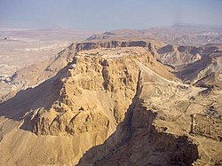
Earth ramp (right) built by Romans in 72 AD to invade Masada, Israel
Burma Road, Assam, India, through Burma to China, c.1945
Inclined planes in a skateboard park
History
Stevin's proof
In 1586, Flemish engineer Simon Stevin (Stevinus) derived the mechanical advantage of the inclined plane by an argument that used a string of beads.[10] He imagined two inclined planes of equal height but different slopes, placed back-to-back as in a prism (A, B, C above). A loop of string with beads at equal intervals is draped over the inclined planes, with part of the string hanging down below. The beads resting on the planes act as loads on the planes, held up by the tension force in the string at point T. Stevin's argument goes like this:[10][11][12]
The string must be stationary, in static equilibrium. If the string was heavier on one side than the other, and began to slide right or left under its own weight, when each bead had moved to the position of the previous bead the string would be indistinguishable from its initial position and therefore would continue to be unbalanced and slide. This argument could be repeated indefinitely, resulting in a circular perpetual motion, which is absurd. Therefore, it is stationary, with the forces on the two sides at point T (above) equal.
The portion of the chain hanging below the inclined planes is symmetrical, with an equal number of beads on each side. It exerts an equal force on each side of the string. Therefore, this portion of the string can be cut off at the edges of the planes (points S and V), leaving only the beads resting on the inclined planes, and this remaining portion will still be in static equilibrium.
Since the beads are at equal intervals on the string, the total number of beads supported by each plane, the total load, is proportional to the length of the plane. Since the input supporting force, the tension in the string, is the same for both, the mechanical advantage of each plane is proportional to its slant length...
As pointed out by Dijksterhuis,[13] Stevin's argument is not completely tight. The forces exerted by the hanging part of the chain need not be symmetrical because the hanging part need not retain its shape when let go. Even if the chain is released with a zero angular momentum, motion including oscillations is possible unless the chain is initially in its equilibrium configuration, a supposition which would make the argument circular.
Inclined planes have been used by people since prehistoric times to move heavy objects.[14][15] The sloping roads and causeways built by ancient civilizations such as the Romans are examples of early inclined planes that have survived, and show that they understood the value of this device for moving things uphill. The heavy stones used in ancient stone structures such as Stonehenge[16] are believed to have been moved and set in place using inclined planes made of earth,[17] although it is hard to find evidence of such temporary building ramps. The Egyptian pyramids were constructed using inclined planes,[18][19][20]Siege ramps enabled ancient armies to surmount fortress walls. The ancient Greeks constructed a paved ramp 6km (3.7 miles) long, the Diolkos, to drag ships overland across the Isthmus of Corinth.[4]
However the inclined plane was the last of the six classic simple machines to be recognised as a machine. This is probably because it is a passive and motionless device (the load is the moving part),[21] and also because it is found in nature in the form of slopes and hills. Although they understood its use in lifting heavy objects, the ancient Greek philosophers who defined the other five simple machines did not include the inclined plane as a machine.[22] This view persisted among a few later scientists; as late as 1826 Karl von Langsdorf wrote that an inclined plane "...is no more a machine than is the slope of a mountain".[21] The problem of calculating the force required to push a weight up an inclined plane (its mechanical advantage) was attempted by Greek philosophers Heron of Alexandria (c. 10 - 60 CE) and Pappus of Alexandria (c. 290 - 350 CE), but their solutions were incorrect.[23][24][25]
It was not until the Renaissance that the inclined plane was solved mathematically and classed with the other simple machines. The first correct analysis of the inclined plane appeared in the work of 13th century author Jordanus de Nemore,[26][27] however his solution was apparently not communicated to other philosophers of the time.[24]Girolamo Cardano (1570) proposed the incorrect solution that the input force is proportional to the angle of the plane.[10] Then at the end of the 16th century, three correct solutions were published within ten years, by Michael Varro (1584), Simon Stevin (1586), and Galileo Galilei (1592).[24] Although it was not the first, the derivation of Flemish engineer Simon Stevin[25] is the most well-known, because of its originality and use of a string of beads (see box).[12][26] In 1600, Italian scientist Galileo Galilei included the inclined plane in his analysis of simple machines in Le Meccaniche ("On Mechanics"), showing its underlying similarity to the other machines as a force amplifier.[28]
The mechanical advantage of an inclined plane depends on its slope, meaning its gradient or steepness. The smaller the slope, the larger the mechanical advantage, and the smaller the force needed to raise a given weight. A plane's slope s is equal to the difference in height between its two ends, or "rise", divided by its horizontal length, or "run".[31] It can also be expressed by the angle the plane makes with the horizontal, .
The inclined plane's geometry is based on a right triangle. The horizontal length is sometimes called Run, the vertical change in height Rise.
Mechanical advantage
The mechanical advantage of a simple machine as defined as the ratio of the output force exerted on the load to the input force applied. The inclined plane the output load force is just the gravitational force of the load object on the plane, its weight . The input force is the force exerted on the object, parallel to the plane, to move it up the plane. The mechanical advantage is
The of an ideal inclined plane without friction is sometimes called ideal mechanical advantage while the MA when friction is included is called the actual mechanical advantage.[32]
Frictionless inclined plane
Instrumented inclined plane used for physics education, around 1900. The lefthand weight provides the load force . The righthand weight provides the input force pulling the roller up the plane.
If there is no friction between the object being moved and the plane, the device is called an ideal inclined plane. This condition might be approached if the object is rolling like a barrel, or supported on wheels or casters. Due to conservation of energy, for a frictionless inclined plane the work done on the load lifting it, , is equal to the work done by the input force, [33][34][35]
Work is defined as the force multiplied by the displacement an object moves. The work done on the load is equal to its weight multiplied by the vertical displacement it rises, which is the "rise" of the inclined plane
The input work is equal to the force on the object times the diagonal length of the inclined plane.
Substituting these values into the conservation of energy equation above and rearranging
To express the mechanical advantage by the angle of the plane,[34] it can be seen from the diagram (above) that
So
So the mechanical advantage of a frictionless inclined plane is equal to the reciprocal of the sine of the slope angle. The input force from this equation is the force needed to hold the load motionless on the inclined plane, or push it up at a constant velocity. If the input force is greater than this, the load will accelerate up the plane. If the force is less, it will accelerate down the plane.
Inclined plane with friction
Where there is friction between the plane and the load, as for example with a heavy box being slid up a ramp, some of the work applied by the input force is dissipated as heat by friction, , so less work is done on the load. Due to conservation of energy, the sum of the output work and the frictional energy losses is equal to the input work
Therefore, more input force is required, and the mechanical advantage is lower, than if friction were not present. With friction, the load will only move if the net force parallel to the surface is greater than the frictional force opposing it.[8][36][37] The maximum friction force is given by
where is the normal force between the load and the plane, directed normal to the surface, and is the coefficient of static friction between the two surfaces, which varies with the material. When no input force is applied, if the inclination angle of the plane is less than some maximum value the component of gravitational force parallel to the plane will be too small to overcome friction, and the load will remain motionless. This angle is called the angle of repose and depends on the composition of the surfaces, but is independent of the load weight. It is shown below that the tangent of the angle of repose is equal to
With friction, there is always some range of input force for which the load is stationary, neither sliding up or down the plane, whereas with a frictionless inclined plane there is only one particular value of input force for which the load is stationary.
Analysis
Key: Fn = N = Normal force that is perpendicular to the plane, Fi = f = input force, Fw = mg = weight of the load, where m = mass, g = gravity
A load resting on an inclined plane, when considered as a free body has three forces acting on it:[8][36][37]
The applied force, exerted on the load to move it, which acts parallel to the inclined plane.
The weight of the load, , which acts vertically downwards
The force of the plane on the load. This can be resolved into two components:
The normal force of the inclined plane on the load, supporting it. This is directed perpendicular (normal) to the surface.
The frictional force, of the plane on the load acts parallel to the surface, and is always in a direction opposite to the motion of the object. It is equal to the normal force multiplied by the coefficient of static friction μ between the two surfaces.
Using Newton's second law of motion the load will be stationary or in steady motion if the sum of the forces on it is zero. Since the direction of the frictional force is opposite for the case of uphill and downhill motion, these two cases must be considered separately:
Uphill motion: The total force on the load is toward the uphill side, so the frictional force is directed down the plane, opposing the input force.
Derivation of mechanical advantage for uphill motion
The equilibrium equations for forces parallel and perpendicular to the plane are
Substituting into first equation
Solving second equation to get and substituting into the above equation
where . This is the condition for impending motion up the inclined plane. If the applied force Fi is greater than given by this equation, the load will move up the plane.
Downhill motion: The total force on the load is toward the downhill side, so the frictional force is directed up the plane.
Derivation of mechanical advantage for downhill motion
The equilibrium equations are
Substituting into first equation
Solving second equation to get and substituting into the above equation
This is the condition for impending motion down the plane; if the applied force Fi is less than given in this equation, the load will slide down the plane. There are three cases:
: The mechanical advantage is negative. In the absence of applied force the load will remain motionless, and requires some negative (downhill) applied force to slide down.
: The 'angle of repose'. The mechanical advantage is infinite. With no applied force, load will not slide, but the slightest negative (downhill) force will cause it to slide.
: The mechanical advantage is positive. In the absence of applied force the load will slide down the plane, and requires some positive (uphill) force to hold it motionless
Mechanical advantage using power
Key: N = Normal force that is perpendicular to the plane, W=mg, where m = mass, g = gravity, and θ (theta) = Angle of inclination of the plane
The mechanical advantage of an inclined plane is the ratio of the weight of the load on the ramp to the force required to pull it up the ramp. If energy is not dissipated or stored in the movement of the load, then this mechanical advantage can be computed from the dimensions of the ramp.
In order to show this, let the position r of a rail car on along the ramp with an angle, θ, above the horizontal be given by
where R is the distance along the ramp. The velocity of the car up the ramp is now
Because there are no losses, the power used by force F to move the load up the ramp equals the power out, which is the vertical lift of the weight W of the load.
The input power pulling the car up the ramp is given by
and the power out is
Equate the power in to the power out to obtain the mechanical advantage as
The mechanical advantage of an inclined plane can also be calculated from the ratio of length of the ramp L to its height H, because the sine of the angle of the ramp is given by
therefore,
Layout of the cable drive system for the Liverpool Minard inclined plane.
Example: If the height of a ramp is H = 1 meter and its length is L = 5 meters, then the mechanical advantage is
which means that a 20lb force will lift a 100lb load.
The Liverpool Minard inclined plane has the dimensions 1804 meters by 37.50 meters, which provides a mechanical advantage of
so a 100lb tension force on the cable will lift a 4810lb load. The grade of this incline is 2%, which means the angle θ is small enough that sinθ≈tanθ.
↑ Scott, John S. (1993). Dictionary of Civil Engineering. Chapman & Hill. p.14. ISBN978-0-412-98421-1. angle of friction [mech.] in the study of bodies sliding on plane surfaces, the angle between the perpendicular to the surface and the resultant force (between the body and the surface) when the body begins to slide. angle of repose [s.m.] for any given granular material the steepest angle to the horizontal at which a heaped surface will stand in stated conditions.
1 2 3 4 Ambekar, A. G. (2007). Mechanism and Machine Theory. PHI Learning. p.446. ISBN978-81-203-3134-1. Angle of repose is the limiting angle of inclination of a plane when a body, placed on the inclined plane, just starts sliding down the plane.
↑ Dutch, Steven (1999). "Pre-Greek Accomplishments". Legacy of the Ancient World. Prof. Steve Dutch's page, Univ. of Wisconsin at Green Bay. Archived from the original on August 21, 2016. Retrieved March 13, 2012.
This page is based on this Wikipedia article Text is available under the CC BY-SA 4.0 license; additional terms may apply. Images, videos and audio are available under their respective licenses.