
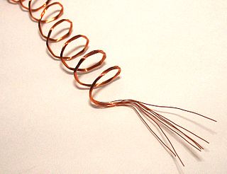
An electromagnetic coil is an electrical conductor such as a wire in the shape of a coil. Electromagnetic coils are used in electrical engineering, in applications where electric currents interact with magnetic fields, in devices such as electric motors, generators, inductors, electromagnets, transformers, and sensor coils. Either an electric current is passed through the wire of the coil to generate a magnetic field, or conversely, an external time-varying magnetic field through the interior of the coil generates an EMF (voltage) in the conductor.

An inductor, also called a coil, choke, or reactor, is a passive two-terminal electrical component that stores energy in a magnetic field when electric current flows through it. An inductor typically consists of an insulated wire wound into a coil.

A transformer is a passive component that transfers electrical energy from one electrical circuit to another circuit, or multiple circuits. A varying current in any coil of the transformer produces a varying magnetic flux in the transformer's core, which induces a varying electromotive force (EMF) across any other coils wound around the same core. Electrical energy can be transferred between separate coils without a metallic (conductive) connection between the two circuits. Faraday's law of induction, discovered in 1831, describes the induced voltage effect in any coil due to a changing magnetic flux encircled by the coil.

A Tesla coil is an electrical resonant transformer circuit designed by inventor Nikola Tesla in 1891. It is used to produce high-voltage, low-current, high-frequency alternating-current electricity. Tesla experimented with a number of different configurations consisting of two, or sometimes three, coupled resonant electric circuits.
In electrical engineering, electrical length is a dimensionless parameter equal to the physical length of an electrical conductor such as a cable or wire, divided by the wavelength of alternating current at a given frequency traveling through the conductor. In other words, it is the length of the conductor measured in wavelengths. It can alternately be expressed as an angle, in radians or degrees, equal to the phase shift the alternating current experiences traveling through the conductor.

A loading coil or load coil is an inductor that is inserted into an electronic circuit to increase its inductance. The term originated in the 19th century for inductors used to prevent signal distortion in long-distance telegraph transmission cables. The term is also used for inductors in radio antennas, or between the antenna and its feedline, to make an electrically short antenna resonant at its operating frequency.

A balun is an electrical device that allows balanced and unbalanced lines to be interfaced without disturbing the impedance arrangement of either line. A balun can take many forms and may include devices that also transform impedances but need not do so. Sometimes, in the case of transformer baluns, they use magnetic coupling but need not do so. Common-mode chokes are also used as baluns and work by eliminating, rather than rejecting, common mode signals.
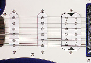
A pickup is a transducer that captures or senses mechanical vibrations produced by musical instruments, particularly stringed instruments such as the electric guitar, and converts these to an electrical signal that is amplified using an instrument amplifier to produce musical sounds through a loudspeaker in a speaker enclosure. The signal from a pickup can also be recorded directly.

A magnetic core is a piece of magnetic material with a high magnetic permeability used to confine and guide magnetic fields in electrical, electromechanical and magnetic devices such as electromagnets, transformers, electric motors, generators, inductors, magnetic recording heads, and magnetic assemblies. It is made of ferromagnetic metal such as iron, or ferrimagnetic compounds such as ferrites. The high permeability, relative to the surrounding air, causes the magnetic field lines to be concentrated in the core material. The magnetic field is often created by a current-carrying coil of wire around the core.

A bifilar coil is an electromagnetic coil that contains two closely spaced, parallel windings. In engineering, the word bifilar describes wire which is made of two filaments or strands. It is commonly used to denote special types of winding wire for transformers. Wire can be purchased in bifilar form, usually as different colored enameled wire bonded together. For three strands, the term trifilar coil is used.

A mast radiator is a radio mast or tower in which the metal structure itself is energized and functions as an antenna. This design, first used widely in the 1930s, is commonly used for transmitting antennas operating at low frequencies, in the LF and MF bands, in particular those used for AM radio broadcasting stations. The conductive steel mast is electrically connected to the transmitter. Its base is usually mounted on a nonconductive support to insulate it from the ground. A mast radiator is a form of monopole antenna.
A loop antenna is a radio antenna consisting of a loop or coil of wire, tubing, or other electrical conductor, that for transmitting is usually fed by a balanced power source or for receiving feeds a balanced load. Within this physical description there are two distinct types:
Litz wire is a particular type of multistrand wire or cable used in electronics to carry alternating current (AC) at radio frequencies. The wire is designed to reduce the skin effect and proximity effect losses in conductors used at frequencies up to about 1 MHz.

In electronics, a choke is an inductor used to block higher-frequency alternating currents (AC) while passing direct current (DC) and lower-frequency ACs in a circuit. A choke usually consists of a coil of insulated wire often wound on a magnetic core, although some consist of a doughnut-shaped ferrite bead strung on a wire. The choke's impedance increases with frequency. Its low electrical resistance passes both AC and DC with little power loss, but its reactance limits the amount of AC passed.

Electrical resonance occurs in an electric circuit at a particular resonant frequency when the impedances or admittances of circuit elements cancel each other. In some circuits, this happens when the impedance between the input and output of the circuit is almost zero and the transfer function is close to one.
Parasitic capacitance is an unavoidable and usually unwanted capacitance that exists between the parts of an electronic component or circuit simply because of their proximity to each other. When two electrical conductors at different voltages are close together, the electric field between them causes electric charge to be stored on them; this effect is capacitance.

A variety of types of electrical transformer are made for different purposes. Despite their design differences, the various types employ the same basic principle as discovered in 1831 by Michael Faraday, and share several key functional parts.

In electromagnetics, proximity effect is a redistribution of electric current occurring in nearby parallel electrical conductors carrying alternating current (AC), caused by magnetic effects. In adjacent conductors carrying AC current in the same direction, it causes the current in the conductor to concentrate on the side away from the nearby conductor. In conductors carrying AC current in opposite directions, it causes the current in the conductor to concentrate on the side adjacent to the nearby conductor. Proximity effect is caused by eddy currents induced within a conductor by the time-varying magnetic field of the other conductor, by electromagnetic induction. For example, in a coil of wire carrying alternating current with multiple turns of wire lying next to each other, the current in each wire will be concentrated in a strip on each side of the wire facing away from the adjacent wires. This "current crowding" effect causes the current to occupy a smaller effective cross-sectional area of the conductor, increasing current density and AC electrical resistance of the conductor. The concentration of current on the side of the conductor gets larger with increasing frequency, so proximity effect causes adjacent wires carrying the same current to have more resistance at higher frequencies.

A microwave cavity or radio frequency cavity is a special type of resonator, consisting of a closed metal structure that confines electromagnetic fields in the microwave or RF region of the spectrum. The structure is either hollow or filled with dielectric material. The microwaves bounce back and forth between the walls of the cavity. At the cavity's resonant frequencies they reinforce to form standing waves in the cavity. Therefore, the cavity functions similarly to an organ pipe or sound box in a musical instrument, oscillating preferentially at a series of frequencies, its resonant frequencies. Thus it can act as a bandpass filter, allowing microwaves of a particular frequency to pass while blocking microwaves at nearby frequencies.

An Ayrton–Perry winding is a type of bifilar winding pattern used in winding wire on forms to make electronic components. Its advantage is that the resulting coil of wire has low values of parasitic inductance and parasitic capacitance. Ayrton–Perry windings of resistance wire are used to make wirewound RF resistors that are used at high frequencies, where inductance and capacitance are unwanted.

