Cross-sectional shape of a wing, blade of a propeller, rotor, or turbine, or sail
Examples of airfoils in nature and in or on various vehicles. The dolphin flipper at bottom left obeys the same principles in a different fluid medium; it is an example of a hydrofoil.Streamlines on an airfoil visualised with a smoke wind tunnel
An airfoil (American English) or aerofoil (British English) is a streamlined body that is capable of generating significantly more lift than drag.[1] Wings, sails and propeller blades are examples of airfoils. Foils of similar function designed with water as the working fluid are called hydrofoils.
When oriented at a suitable angle, a solid body moving through a fluid deflects the oncoming fluid (for fixed-wing aircraft, a downward force), resulting in a force on the airfoil in the direction opposite to the deflection.[2][3] This force is known as aerodynamic force and can be resolved into two components: lift (perpendicular to the remote freestream velocity) and drag (parallel to the freestream velocity).
The lift on an airfoil is primarily the result of its angle of attack. Most foil shapes require a positive angle of attack to generate lift, but cambered airfoils can generate lift at zero angle of attack. Airfoils can be designed for use at different speeds by modifying their geometry: those for subsonic flight generally have a rounded leading edge, while those designed for supersonic flight tend to be slimmer with a sharp leading edge. All have a sharp trailing edge.[4]
The deflection of air by an airfoil generates a lower-pressure region above and behind itself. This pressure difference is accompanied by a velocity difference, via Bernoulli's principle, so the resulting flowfield about the airfoil has a higher average velocity on the upper surface than on the lower surface.[5] In some situations (e.g., inviscidpotential flow) the lift force can be related directly to the average top/bottom velocity difference without computing the pressure by using the concept of circulation and the Kutta–Joukowski theorem.[6]
Overview
Streamlines around a NACA 0012 airfoil at moderate angle of attackLift and drag curves for a typical airfoil
The wings and stabilizers of fixed-wing aircraft, as well as helicopter rotor blades, are built with airfoil-shaped cross sections. Airfoils are also found in propellers, fans, compressors and turbines. Sails are also airfoils, and the underwater surfaces of sailboats, such as the centerboard, rudder, and keel, are similar in cross-section and operate on the same principles as airfoils. Swimming and flying creatures and even many plants and sessile organisms employ airfoils/hydrofoils, common examples being bird wings, the bodies of fish, and the shape of sand dollars. An airfoil-shaped wing can create downforce on an automobile or other motor vehicle, improving traction.
When the wind is obstructed by an object such as a flat plate, a building, or the deck of a bridge, the object will experience drag and also an aerodynamic force perpendicular to the wind. This does not mean the object qualifies as an airfoil. Airfoils are highly-efficient lifting shapes, able to generate more lift than similarly sized flat plates of the same area, and able to generate lift with significantly less drag. Airfoils are used in the design of aircraft, propellers, rotor blades, wind turbines and other applications of aeronautical engineering.
A lift and drag curve obtained in wind tunnel testing is shown on the right. The curve represents an airfoil with a positive camber so some lift is produced at zero angle of attack. With increased angle of attack, lift increases in a roughly linear relation, called the slope of the lift curve. At about 18 degrees this airfoil stalls, and lift falls off quickly beyond that. The drop in lift can be explained by the action of the upper-surface boundary layer, which separates and greatly thickens over the upper surface at and past the stall angle. The thickened boundary layer's displacement thickness changes the airfoil's effective shape, in particular it reduces its effective camber, which modifies the overall flow field so as to reduce the circulation and the lift. The thicker boundary layer also causes a large increase in pressure drag, so that the overall drag increases sharply near and past the stall point.
Airfoil design is a major facet of aerodynamics. Various airfoils serve different flight regimes. Asymmetric airfoils can generate lift at zero angle of attack, while a symmetric airfoil may better suit frequent inverted flight as in an aerobatic airplane. In the region of the ailerons and near a wingtip a symmetric airfoil can be used to increase the range of angles of attack to avoid spin–stall. Thus a large range of angles can be used without boundary layer separation. Subsonic airfoils have a round leading edge, which is naturally insensitive to the angle of attack. The cross section is not strictly circular, however: the radius of curvature is increased before the wing achieves maximum thickness to minimize the chance of boundary layer separation. This elongates the wing and moves the point of maximum thickness back from the leading edge.
Supersonic airfoils are much more angular in shape and can have a very sharp leading edge, which is very sensitive to angle of attack. A supercritical airfoil has its maximum thickness close to the leading edge to have a lot of length to slowly shock the supersonic flow back to subsonic speeds. Generally such transonic airfoils and also the supersonic airfoils have a low camber to reduce drag divergence. Modern aircraft wings may have different airfoil sections along the wing span, each one optimized for the conditions in each section of the wing.
Movable high-lift devices, flaps and sometimes slats, are fitted to airfoils on almost every aircraft. A trailing edge flap acts similarly to an aileron; however, it, as opposed to an aileron, can be retracted partially into the wing if not used.
For many wings, the boundary layer of the air flow close to the upper surface rapidly becomes turbulent past the maximum thickness point, which increases the skin friction drag. A laminar flow wing moves the maximum thickness point well back along the chord from a typical 25% chord position from to 60% from the leading edge or more.[7] This maintains smooth laminar flow over a larger percentage of the wing and significantly reduces drag. However, surface contamination will disrupt the boundary layer, making it turbulent. Insects, for example, impacting and sticking onto the wing will cause the loss of wedge shaped regions of laminar flow across the wing's surface. This is a particular problem for aircraft with high take off speeds, since many insects are found near the ground making it unlikely that laminar flow can be sustained into the flight.[8]Gliders have seen widespread uptake of laminar flow airfoils due to their low speeds and need for low drag aerodynamic structures.[7]
Before NASA's research in the 1970s and 1980s laminar flow wing designs were not practical using common manufacturing tolerances and surface imperfection, until new manufacturing methods were developed with machined metal and composite materials (e.g. laminar-flow airfoils developed by Professor Franz Wortmann for use with wings made of fibre-reinforced plastic). NASA's research in the 1980s revealed the practicality and usefulness of laminar flow wing designs and opened the way for laminar-flow applications on modern practical aircraft surfaces, from subsonic general aviation aircraft to transonic large transport aircraft, to supersonic designs.[9]
Schemes have been devised to define airfoils – an example is the NACA system. Various airfoil generation systems are also used. An example of a general purpose airfoil that finds wide application, and pre–dates the NACA system, is the Clark-Y. Today, airfoils can be designed for specific functions by the use of computer programs.
Airfoil terminology
Airfoil nomenclature
The various terms related to airfoils are defined below:[10]
The suction surface (typically upper surface) is generally associated with higher velocity and lower static pressure.
The pressure surface (typically lower surface) has a comparatively higher static pressure than the suction surface. The pressure gradient between these two surfaces contributes to the lift force generated for a given airfoil.
The geometry of the airfoil is described with a variety of terms:
The leading edge is the point at the front of the airfoil that has maximum curvature (minimum radius).[11]
The trailing edge is the point on the airfoil most remote from the leading edge. The angle between the upper and lower surfaces at the trailing edge is the trailing edge angle.
The chord line is the straight line connecting leading and trailing edges. The chord length, or simply chord, , is the length of the chord line. That is the reference dimension of the airfoil section.
Different definitions of airfoil thicknessAn airfoil designed for winglets (PSU 90-125WL)
The shape of the airfoil is defined using the following geometrical parameters:
The mean camber line or mean line is the locus of points midway between the upper and lower surfaces. Its shape depends on the thickness distribution along the chord;
The thickness of an airfoil varies along the chord. It may be measured in either of two ways:
Thickness measured perpendicular to the camber line.[12][13] This is sometimes described as the "American convention";[12]
Thickness measured perpendicular to the chord line.[14] This is sometimes described as the "British convention".
Some important parameters to describe an airfoil's shape are its camber and its thickness. For example, an airfoil of the NACA 4-digit series such as the NACA 2415 (to be read as 2 – 4 – 15) describes an airfoil with a camber of 0.02 chord located at 0.40 chord, with 0.15 chord of maximum thickness.
Finally, important concepts used to describe the airfoil's behaviour when moving through a fluid are:
The aerodynamic center, which is the chord-wise location about which the pitching moment is independent of the lift coefficient and the angle of attack.
The center of pressure, which is the chord-wise location about which the pitching moment is momentarily zero. On a cambered airfoil, the center of pressure is not a fixed location as it moves in response to changes in angle of attack and lift coefficient.
In two-dimensional flow around a uniform wing of infinite span, the slope of the lift curve is determined primarily by the trailing edge angle. The slope is greatest if the angle is zero; and decreases as the angle increases.[15][16] For a wing of finite span, the aspect ratio of the wing also significantly influences the slope of the curve. As aspect ratio decreases, the slope also decreases.[17]
Thin airfoil theory
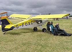
An airfoil section is displayed at the tip of this Denney Kitfox aircraft, built in 1991.Airfoil of a Kamov Ka-26 helicopter's lower rotor blade
Thin airfoil theory is a simple theory of airfoils that relates angle of attack to lift for incompressible, inviscid flows. It was devised by German mathematician Max Munk and further refined by British aerodynamicist Hermann Glauert and others[18] in the 1920s. The theory idealizes the flow around an airfoil as two-dimensional flow around a thin airfoil. It can be imagined as addressing an airfoil of zero thickness and infinite wingspan.
Thin airfoil theory was particularly notable in its day because it provided a sound theoretical basis for the following important properties of airfoils in two-dimensional inviscid flow:[19][20]
on a cambered airfoil, the aerodynamic center lies exactly one quarter of the chord behind the leading edge, but the position of the center of pressure moves when the angle of attack changes.
the slope of the lift coefficient versus angle of attack line is units per radian.
As a consequence of (3), the section lift coefficient of a thin symmetric airfoil of infinite wingspan is:
(The above expression is also applicable to a cambered airfoil where is the angle of attack measured relative to the zero-lift line instead of the chord line.)
Also as a consequence of (3), the section lift coefficient of a cambered airfoil of infinite wingspan is:
where is the section lift coefficient when the angle of attack is zero.
Thin airfoil theory assumes the air is an inviscid fluid so does not account for the stall of the airfoil, which usually occurs at an angle of attack between 10° and 15° for typical airfoils.[21] In the mid-late 2000s, however, a theory predicting the onset of leading-edge stall was proposed by Wallace J. Morris II in his doctoral thesis.[22] Morris's subsequent refinements contain the details on the current state of theoretical knowledge on the leading-edge stall phenomenon.[23][24] Morris's theory predicts the critical angle of attack for leading-edge stall onset as the condition at which a global separation zone is predicted in the solution for the inner flow.[25] Morris's theory demonstrates that a subsonic flow about a thin airfoil can be described in terms of an outer region, around most of the airfoil chord, and an inner region, around the nose, that asymptotically match each other. As the flow in the outer region is dominated by classical thin airfoil theory, Morris's equations exhibit many components of thin airfoil theory.
Laminar flow airfoil for a crewed propeller aircraft
Laminar flow at a jet airliner airfoil
Stable airfoil used for flying wings
Aft loaded airfoil allowing for a large main spar and late stall
Transonic supercritical airfoil
Supersonic leading edge airfoil
laminar flow
turbulent flow
subsonic stream
supersonic flow volume
In thin airfoil theory, the width of the (2D) airfoil is assumed negligible, and the airfoil itself replaced with a 1D blade along its camber line, oriented at the angle of attackα. Let the position along the blade be x, ranging from 0 at the wing's front to c at the trailing edge; the camber of the airfoil, dy⁄dx, is assumed sufficiently small that one need not distinguish between x and position relative to the fuselage.[26][27]
The flow across the airfoil generates a circulation around the blade, which can be modeled as a vortex sheet of position-varying strength γ(x). The Kutta condition implies that γ(c)=0, but the strength is singular at the bladefront, with γ(x)∝1⁄√x for x≈ 0.[28] If the main flowV has densityρ, then the Kutta–Joukowski theorem gives that the total lift force F is proportional to[29][30]and its moment M about the leading edge proportional to[28]
From the Biot–Savart law, the vorticity γ(x) produces a flow field oriented normal to the airfoil at x. Since the airfoil is an impermeable surface, the flow must balance an inverse flow from V. By the small-angle approximation, V is inclined at angle α-dy⁄dx relative to the blade at position x, and the normal component is correspondingly (α-dy⁄dx)V. Thus, γ(x) must satisfy the convolutionequation which uniquely determines it in terms of known quantities.[29][31]
An explicit solution can be obtained through first the change of variablesand then expanding both dy⁄dx and γ(x) as a nondimensionalized Fourier series in θ with a modified lead term: The resulting lift and moment depend on only the first few terms of this series.[32]
The lift coefficient satisfies and the moment coefficient[33] The moment about the 1/4 chord point will thus be From this it follows that the center of pressure is aft of the 'quarter-chord' point 0.25c, by The aerodynamic center is the position at which the pitching moment M′ does not vary with a change in lift coefficient:[29] Thin-airfoil theory shows that, in two-dimensional inviscid flow, the aerodynamic center is at the quarter-chord position.
↑Halliday & Resnick 1988, p.378: "The effect of the wing is to give the air stream a downward velocity component. The reaction force of the deflected air mass must then act on the wing to give it an equal and opposite upward component."
↑Hall, NancyR. "Lift from Flow Turning". NASA Glenn Research Center. Archived from the original on 5 July 2011. Retrieved 2011-06-29. If the body is shaped, moved, or inclined in such a way as to produce a net deflection or turning of the flow, the local velocity is changed in magnitude, direction, or both. Changing the velocity creates a net force on the body.
↑“It has been known from the very beginning of flight that wings with a sharp trailing edge must be used in order to obtain a well-defined lift.” von Mises, Richard (1945), Theory of Flight, Section VIII.2, p.179, Dover Publications Inc. ISBN 0-486-60541-8
↑Hurt, H. H. Jr. (January 1965) [1960]. Aerodynamics for Naval Aviators. U.S. Government Printing Office, Washington, D.C.: U.S. Navy, Aviation Training Division. pp.21–22. NAVWEPS 00-80T-80.
↑Lyons, D.J., and Bisgood, P.L., (Jan 1945). An analysis of the lift slope of aerofoils of small aspect ratio. Reports and Memoranda of the Aeronautical Research Council of Great Britain No 2308
↑Abbott, I.H., and Von Doenhoff, A.E. (1949) Theory of Wing Sections, section 7.4(b)
↑Abbott, I.H., and Von Doenhoff, A.E. (1949) Theory of Wing Sections, section 1.3
↑Scott 2003: "The equation can only be used for aircraft with medium to large aspect ratio wings and only up to the stall angle, which is usually between 10° and 15° for typical aircraft configurations."
↑Ramesh, Kiran; Gopalarathnam, Ashok; Granlund, Kenneth; Ol, Michael V.; Edwards, Jack R. (July 2014). "Discrete-vortex method with novel shedding criterion for unsteady aerofoil flows with intermittent leading-edge vortex shedding". Journal of Fluid Mechanics. 751: 500–538. Bibcode:2014JFM...751..500R. doi:10.1017/jfm.2014.297. ISSN0022-1120. S2CID121962230.
↑Auld & Srinivas 1995: "A simple solution for general two-dimensional aerofoil sections can be obtained by neglecting thickness effects and using a mean-line only section model.... This also means small changes in position are equivalent so that ds≈dx."
Morris, Wallace J. II (2009). A universal prediction of stall onset for airfoils at a wide range of Reynolds number flows (PhD). Harvard University. Bibcode:2009PhDT.......146M.
Bearman, Matt (2019). "Going with the Flow? Britain's Contribution to Laminar-Flow Research, 1930–1947". The Aviation Historian (29): 74–87. ISSN2051-1930.
This page is based on this Wikipedia article Text is available under the CC BY-SA 4.0 license; additional terms may apply. Images, videos and audio are available under their respective licenses.